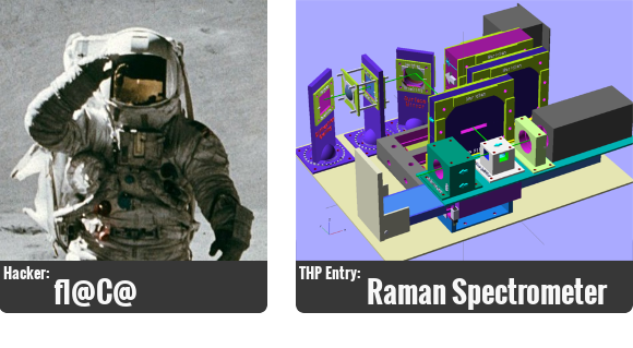
 Now that we’re starting to get serious about The Hackaday Prize we thought we’d take a look at the lives of some of the hackers who have submitted entries. Meet fl@C@, who is working on a Raman Spectrometer which is largely 3D printed and uses a Raspberry Pi. He was kind enough to answer all of our questions, some serious and some not so.
![]()
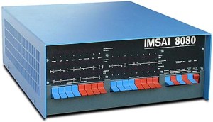
Creating. It’s probably no surprise that I have many hobbies…but hardware hacking is my life. I got my first taste with my dads Imsai 8080 (showing my age, but I was fairly young!)..Then it was an Apple][.. I really dove into that. I built my own from a bare pcb to a working machine when I was around 11 or 12. Just moved up from there.. Really went nuts when I got a job at a surplus electronics store in the silicon valley.. I rarely took home a paycheck.. I have a few other hobbies, I’m a private pilot…love flying. I built a pretty cool device that allowed me to datalog my flights, my heartrate, keep track of the fuel, it speaks and connects to the comm to remind me when to switch tanks, etc.. I’ll have to put that up on the project page.
![]() Well…For my day job, I am a Network Engineer.. I can’t really say for which company, but it’s big.
Well…For my day job, I am a Network Engineer.. I can’t really say for which company, but it’s big.
![]()
My Passion is Going Big
I would say my passion is going big..if it’s worth doing…..it’s worth overdoing. I love coming up with ideas that would make a difference. The spectrometer I am working on is actually only a small part of a larger project I am working toward. There are never enough hours, or dollars to cover all of my ideas…but I always work as hard as I can to get there.. TLDR- I’m excited every day to wake up and make another step towards changing the world.
![]() I work from home, but in the office… it’s definitely the snack machine. Seriously? We can’t build a machine that dispenses snacks without getting them stuck?
I work from home, but in the office… it’s definitely the snack machine. Seriously? We can’t build a machine that dispenses snacks without getting them stuck?
![]() I’d say linux. I’ve been a fan of ubuntu for a while.. lately I’ve been playing with xubuntu. I don’t care for messing with computers..lol.
I’d say linux. I’ve been a fan of ubuntu for a while.. lately I’ve been playing with xubuntu. I don’t care for messing with computers..lol.  I love electronics, hardware, software and all that.. but I do not geek out over PC hardware..I consider them another tool…they need to work when I need them to work. lol
![]() Not sure if you want a breakdown of what gear I have….I have quite a bit and a pretty elaborate lab setup..but I’m really a bit of a minimalist when it comes to day to day use.. I use my scope when it’s appropriate..my logic analyzer (saelae logic rocks) pretty often.. but I’d say my go to device is usually my DMM since it’s what I tend to use most often…I have a few, but I like to use the one that connects up to my PC so I can make screenshots, and/or see it from a distance..
Not sure if you want a breakdown of what gear I have….I have quite a bit and a pretty elaborate lab setup..but I’m really a bit of a minimalist when it comes to day to day use.. I use my scope when it’s appropriate..my logic analyzer (saelae logic rocks) pretty often.. but I’d say my go to device is usually my DMM since it’s what I tend to use most often…I have a few, but I like to use the one that connects up to my PC so I can make screenshots, and/or see it from a distance..
![]()
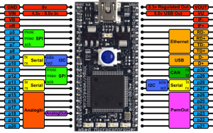 I would have to default to the mBed for this one..for general purpose. I started out like most people probably with the basic stamp waaaay back…and went through a few others..and settled on the mBed when there was just one device, but now they have so many platforms that you can fit to whatever need..and some of them are dirt cheap. I’m using the ST Nucleo041RE for the spectrometer project, and it’s only $10 at mouser. I have just started peering into FPGA stuff, I hope to get some more time to work with them very soon, I see lots of potential.. I never really used Arduino’s until the past year or two when I got into quadcopters..they have a purpose..and are ok for quick and dirty stuff since you can source a pro mini on ebay for like 3 bucks..
![]() Python has become my best friend. C++ is great and all, I’ve been forced to use VB6 for work…where they even use winbatch……. But python works.. and it’s easy to crank something out quickly, and you can build some pretty robust stuff with it..
Python has become my best friend. C++ is great and all, I’ve been forced to use VB6 for work…where they even use winbatch……. But python works.. and it’s easy to crank something out quickly, and you can build some pretty robust stuff with it..
![]() Well, I have a couple that come to mind immediately that I honestly would love to share with the world…but won’t just yet.. =) So, I’ll go with what is left…hopefully it’s plenty for now..
Well, I have a couple that come to mind immediately that I honestly would love to share with the world…but won’t just yet.. =) So, I’ll go with what is left…hopefully it’s plenty for now..
- I’d love to build a fusor. I built my first tesla coil when I was 17.. I’d love to take the hobby fusor to the next step..
- A Moon Rover. Seriously. And the vehicle to get it there. I think we all agree rockets and gasoline both need to go away. Mankind needs to reach out beyond what we’re confortable with.
- A fully autonomous multirotor. I actually started this project..have it all layed out..but it’s not high enough on my priority list to make it the rest of the way..I have probably 80% of the parts new in a box..I’ve started doing a writeup on it..and hope to get it up soon.
![]()
Learn the Value of Knowing Where and How to Find the Information [You] need
I wish that everyone would learn the value of knowing where and how to find the information they need to accomplish a goal. Schools typically force you to memorize facts and information that is often worthless. I would like for people to learn instead how to be adaptive in their approach to problems, and understand that there is always more than one answer.. and there is a huge resource out there that will enable you to make educated decisions and reach grander goals. We live in a great time with that…and in that way, the internet is underutilized…
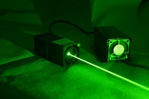
![]() The timing was right…I thought this was an interesting and unique project..I had promised myself to try to be more open and share..this project was perfect since it has 3d parts people can print themselves, a raspberryPi, a sorta arduino and a cool laser…plus I figured there are several people out there that could either benefit from a low cost raman spectrometer, or at least benefit from some part of it..be it the parts I designed or just the understanding of how it works and what they’re used for…
The timing was right…I thought this was an interesting and unique project..I had promised myself to try to be more open and share..this project was perfect since it has 3d parts people can print themselves, a raspberryPi, a sorta arduino and a cool laser…plus I figured there are several people out there that could either benefit from a low cost raman spectrometer, or at least benefit from some part of it..be it the parts I designed or just the understanding of how it works and what they’re used for…
![]()
 I always keep an open mind, and consider any advice given.. There have been many aspects of this project that created a challenge.. This is my first serious venture into 3d printing this much stuff…I’ve never really worked with lasers and optics in such a way.. Avoiding spending thousands on optics was a major challenge. I have been doing all the research I can to understand the best approach to imaging…My first idea was to modify a webcam to take long exposures since the light reaching the camera will be fairly faint..after looking into that, it’s not just a lot of work and difficult to reproduce…but the cameras that others have modified are ancient and next to impossible to find. I wanted to go with a camera that anyone could find…the raspiCam kept surfacing as the best choice…so, the next challenge was how to get the long exposure…the raspiCam driver doesn’t really allow for 10-30 second exposures… so the next idea was to take several shots, and stack them to build a usable image.. so my latest approach is to take a 90fps video for a couple seconds, split that into individual frames, and stack those.. If anyone has suggestions in this area, I’d love to hear them.. I planned on using either mathematica or qtoctave from python, etc..
![]()
 A Moon Rover. =) It’d probably most definately be a team effort.. But I think as a community, the skills are out there. And the google XPrize shouldn’t be the only game in town.. I think things are building up to this kind of stuff anyway, but someone’s got to be first.
![]()
Live Out Loud Every Day
![]() I’d just like to say…putting this project on this site was a major debate for me. I grew up with parents that had secret clearances, and privacy was central. I’ve been trying to build up the courage to share my work and ideas with the world because I think it benefits everyone. This project is my first to share, and for it to be featured here, and for me to be honored with being the first the be featured is really amazing. I appreciate this whole community, I’ve learned a lot from it over the years and I hope to be able to give back and contribute more soon!
I’d just like to say…putting this project on this site was a major debate for me. I grew up with parents that had secret clearances, and privacy was central. I’ve been trying to build up the courage to share my work and ideas with the world because I think it benefits everyone. This project is my first to share, and for it to be featured here, and for me to be honored with being the first the be featured is really amazing. I appreciate this whole community, I’ve learned a lot from it over the years and I hope to be able to give back and contribute more soon!


For anyone searching the mbed board, I think he meant ST Nucleo 401RE…
“split that into individual frames, and stack those”
Amateur astronomers usually do that with cheap webcams. A good point is that is also possible, with proper algorithms, cancelling the noise very well.
Use an old Canon camera with CHDK-PTP to interface with it and transfer the photos? Any exposure time you want up to half an hour. The lens assembly can be removed and CHDK can trick the camera into thinking it’s still there.
I had considered this.. The problem being the limited space inside, and I’d really like to keep this as easy to reproduce as possible..the raspi cam is so easy to find and it’s tiny..
If you’re going to go with a camera (CCD, etc.. ) it might be a good idea to attempt to keep it cool(er) than ambient (possibly using a peltier) to help reduce noise (I’m sure you don’t want to think about using LN2. ;)
Otherwise, you’d be better off (from a signal-to-noise standpoint) to go with a sensitive photodiode, and sweep the diffracted spectrum across a slit in front of the diode. It takes longer, but you’ll likely get better acquisition times and better sensitivity at the cost a bit more complexity (think along the lines of a ‘traditional’ monochromator).
Also, have you considered turning the entire box on it’s side to make use of the 5.25″ bay for the cuvette? ;)
I had looked into the photodiode and the sweeping slit.. At the time, it seemed like a less elegant solution.. but the points about the snr do raise some concern.. I know I can work some of that out with software, etc.. I think I’m going to try some testing…
When I originally was looking at modifying a webcam for long exposure, I’d assumed I was going to have to cool it with a peltier… but I hadn’t thought of cooling one to reduce the noise..that’s a great point and I will try some experiments with that..
You know, it’s funny..sometimes when an answer is right in front of your face…sitting the whole case on its side would totally work.. I’d thought about using it, but since it was a single bay…I stopped there and moved to other stuff.. haha.. I’m going to consider that.. My first concern is the other effects of everything being on it’s side after having kinda designed it all to be standing the way I did… I’ll look and see if there’d be any detrimental effects.. Thanks!
You could try using a linear CCD from a scanner. These have quite many points, are fairly easy to read (just feed it with the clock pulses according to the datasheet and read the analog data from the pixels with a 12-bit ADC), and you have a lot of control over the exposure. I played with one some years ago and managed to get the data out easily with an ATmega8 chip (the on-chip ADC was a bit too slow, though), though there was a problem with a rather low light sensitivity of the type I used (some lousy scanner or fax kind, $1 a piece on eBay).
From your design, it looks like it should be just fine – though some additional stiffening on your optics mounts might not be a bad idea.
.. another thing to consider (in relation to sensitivity) is how much light you collect from your sample. Since you’re measuring back-scattered Raman, it’s not a bad idea to get as much as possible. I saw a setup at University of Bordeaux which used an old Nikon f/1.4 turned around (film-side of the lens images the sample in ‘macro mode’) to get the largest solid angle of collection. This setup however used a side-scatter configuration, so it may not be entirely suitable for you. Plus, you’ll have to expand the beam form the laser to fill (as much as possible) the input aperture of the lens (not such an easy task in a confined space such as yours). Also may not be an option from a DIY standpoint, since I don’t know how available these old lenses are (the one I’m referring to would fit on pre-F model Nikon film cameras – this was a predecessor to the nikon F-mount).
That sounds interesting… I was thinking about the stiffness too actually… The mounts I’ve printed are surprisingly stiff…having said that…vibrations in the case from fans, motors, or whatever else… maybe even noise in the room seem like they might cause some resonance, since if you flick them they do ring a tiny bit.. I’ll look into that too since your previous comment about using the 5,25″ drive bay with the case on its side has sent me into a tailspin of re-design considerations…. I’ve been playing around with different configurations for all of the optics, etc.. I’m pretty confident it’d work if I sat it on its side…I might have to include another mirror, maybe two….but I think it’d work out nicely…and that would save the heartbreak of either cutting a hole in the front of the case or figuring out another solution… It’s sad too because I just finished a really nice version of the 5.25″ TFT and keypad mount…which will now probably end up in another project..
That lens configuration sounds like it has some considerable advantages.. but yes…I agree, sourcing the old lenses as well as the probably expense and space constraints might exclude it… However…I’m wondering if there isn’t still a way to implement some kind of side scatter config… I might look more into this if the return I’m getting is proving difficult… I’d rather go with as few optics as possible…
.. or if you want to get *really* sensitive, you can always pick up a new-old-stock photomultiplier tube on ebay. You won’t have to worry about cooling, but you’ll need HV to drive the tube (and maybe a good ADC).
I’m pretty sure every spectrometer built in the last decade uses linear CCDs or maybe a few linear CMOS chips to avoid HV needs. If you’re starting an opensource project you’d need the major sensor to be widely available which will likely not be the case with surplus PMTs.
Not necessarily. The latest models from HORIBA often use PMTs and photodiodes (usually cooled with LN2 for the latter) simply because of cost. You can, of course, get additional detectors such as a back-thinned peltier cooled CCD, but at a cost of upwards of $50k USD. It all depends on the application. If you require very high sensitivity (which is usually the case for very weak Raman signals) then the PMD or photodiode is the way to go. If however, you want spectral information versus spatial position, then the 2D CCD array is the way to go.
I only mention the PMT because they’re widely available, and usually pretty cheap. Plus, there is absolutely NOTHING out there (well, very little) that can beat the sensitivity of PMTs (think single photon detection). ;)
Ah, almost forgot the link:
http://www.horiba.com/scientific/products/optical-spectroscopy/spectrometers-monochromators/
Not sure we needed the entirety of the article on the front page, chaps…
Yep, but since this was the first one I wanted everyone to know how much there is to this format. I’ll figure out where to put the “more” tag next week.
Regarding tips for the video… Not sure if its available for the Pi but OpenCV has specific functions to split apart a video into images, stack the images, add them with floating point accuracy using vector instructions, as well as sub-pixel transforms that might be useful to you – with that many images you might be able to do some super-resolution tricks on top of the image stacking.
I’ve played with openCV on the Pi..for another project… I’ll take a look again, hopefully this functionality would be faster than what I was trying to do previously on the Pi.. I think this would definitely benefit from any resolution boost I can muster..
You might want to use a black and white camera for your detector. The bayer filter on a color CCD will drastically attenuate your signal.
That’s a great point actually… But poses another issue, unless I’m missing something…how would I pick up the full spectrum of returned light…I think that’d at least require some calibration for the position of each pixel….? I had actually considered the raspi noir cam as a selectable secondary option…something like a regular usb webcam as the primary and the noir 2nd mounted in a way that you could switch between them.. The other option is to just use a linear ccd array…that’s what I think they use in the bigger machines.. But I wanted to make this as simple to build and get parts for as possible, and was hoping I could play as many tricks with the software as I could to compensate for the cameras shortcoming..
I just want to say that your projects are impressive, and I have a lot of respect for what you are doing. In regards to your choice of camera, I have to agree with jk. I would suggest you look for a usb monochrome CCD, perhaps something typically used for astronomy. Well depth and dark current will limit your capabilities, especially for something like a 90s exposure.
To address the spectrum measuring capabilities, you could use a rotating filter wheel with bandpass filters for each color space. You’ll have to compensate for the varying quantum efficiency, but any ccd manufacturer worth their salt will have the data readily available.
You can always try to pick up an older Philips 3CCD, which uses a prism to split incoming light onto three separate CCDs.
Good luck, I look forward to seeing more projects from you.
I just forgot to mention that a series of quick exposures is going to contribute a ton of noise to your image if the intensity is relatively low. (Since it’s Raman scatter, I’d imagine it is pretty low signal)
Basically, every time you read out the pixels, you are contributing noise to the signal. Ninety 1s exposures will contribute 90X the noise that a single 90s exposure and subsequent readout would.
Won’t leaving the sensor collecting for 90s cause heating leading to the same introduction of noise? Even with cooling there’s going to be some threshold where the noise is too high or the values to different to be comparable/useful.
Sounds like some trial and error will be needed to find the sweet spot.
You are correct: Regardless of which type of CCD you use, you’ll need a way to calibrate pixel position to the wavelength of your dispersed spectrum. With traditional monochromators, this is typically done with a known reference spectrum (i.e. mercury lamp) but it can also be done using a CFL, since they contain enough mercury to generate well defined bands.
Jason: Thank you.. I appreciate the compliment. I see your and jk’s point. I’m going to have to do more research on camera modules.. I’d really like to keep cost to a minimum so more people could have a chance at building one.. My niece wants to win the science fair! I’ve been up and down a lot of astronomy site in the past few days and I wonder about resolution too..it seems anything with a higher pixel count is very expensive.. Do you think the raspi noir camera with a rotating filter wheel would be an acceptable middle of the road option? Since I only have 6 cubic inches remaining to work in..I have some space constraints as well.. With the raspi camera I hadn’t planned on taking a 90 second exposure…but rather a 90frames per second video…splitting that into individual frames and then stacking them with some processing along the way… I understand there’ll be an additive effect and the noise will increase as I go… so nothing gained I suppose over a 90second exposure.. I knew this was going to be the major challenge with this project.. :)
medix: Thank you, that’s also a great point! I had forgotten…CFL should be a great option too since most people can pick one up at the local store…or amazon, etc..
From what I can tell, the only difference between the Raspi Noir and the standard camera is that the Noir has no IR filter. If you have the Noir, stick with it, because that IR filter is definitely going to knock down your signal intensity (Even in the passband you’ll still probably loose ~10%).
The truth is that I can’t really say whether or not the camera will do it. It’s all about your signal to noise. I looked up the OV5647 sensor datasheet, and the specs listed don’t give any information about the readout noise. Apparently though, this is a CMOS sensor, which is typically going to have more readout noise than an equivalent CCD. The dark noise is given at 8 mV/s at 50C, which is pretty high. I see you are cooling it, which will help but definitely limits long exposures. I think that’s actually the major limitation (and why you can’t do a very long exposure).
So, I’d say, bin the pixels at least 2 x 2 and shoot for a ~1s exposure. Also, based on your optical layout, do you really need full color to get spectral data? Isn’t the point of using the diffraction grating to separate wavelengths spatially?
Jason: I couldn’t respond to your reply…I think it only goes so deep… But…
I do think I either need full color or some trickery like the filter wheel with multiple exposures to get everything with a black and white camera..like medix said above, I’ll have to calibrate using a known lightsource.. I’m beginning to wonder if the best middle ground is a linear CCD setup…but the drawback again is that instantly eliminates a lot of people from being able to build one.. I think Leithoa is right, there’s probably going to be some experimenting required…
Yes btw- my layout does use a reflective grating surface…which spreads out the wavelengths spatially…My design is obviously maturing and things are coming to light (pardon the pun) that might alter it a little…but I think the majority is workable.. I went back and forth with the raspi camera already…and ultimately I really want to be able to keep this in the realm of possibility for as many people as possible while still finding the balances..
So I have a couple takeaways so far….
1. Cooling… probably a good idea, eliminate as much noise as possible before having to do it with software..
2. Consider attenuation with color imagers..
The one thing that remains in the back of my mind here… the power of the laser hasn’t been considered here… While I’m sure that the eBay 150mw 532nm laser is anything but 150mw at 532nm..and probably has a bunch of IR, etc…which hopefully gets filtered out with the pass filter…but the more laser power, the more raman scattering and more return you get… I’m sure there’s a lot of math to calculate how much light I’ll get to use after hitting the beam splitter, going through the edge filters, and so on…all the way to the grating surface….but one nice thing I’ve tried to engineer into this thing is that it’s modular… So, if one imager doesn’t work out… I can just whip up another mount until I find a workable solution..
I really appreciate the input on this.. I will definitely be keeping my eyes open for any input that anyone has…and I’ll be posting all my progress on hackaday.io .. :)
CFL may be a little problem due to the phosphor. There will be a lot of light from that; the mercury lines are likely to be drown in it. Partial improvement can be achieved by using light from the part of tubes just at the end, where there’s no phosphor and the blue glow is visible there, but the diffuse light from the phosphor will still be an issue.
Consider using a neon bulb? Fewer lines, but these are quite well defined and the bulb is cheap, small, and easy to feed. The 540.1, 585.2, 588.2, 603.0, and 607.4 may be all that’s needed. Maybe just the first three, depending on the band the spectrometer will cover.
Or you can opt for a low-pressure sodium lamp. The doublet of the lines is within the desired range for the green laser, it is strong, and very well defined at 589.0 and 589.6 nm. There are also some other sodium lines there, and some neon and argon lines from the buffer gas.
The parasitic IR from the ebay green laser should not be a problem. It is far away from the Raman scattering band (both the 880 and 1064nm peaks), and if you take care about not bouncing it around in the enclosure and finding ways to the sensor, the grating should deflect it away. (The optics not focusing it well could wreak havoc there, though. In the case it becomes a problem, you may like bouncing the laser beam itself off another grating, which can be of lower quality, and deflect the offending wavelengths away.)
With relatively high power lasers and long acquisition times, beware of the possibility of frying the sample. Thermal damage is possible. I am not sure how much would the Raman lines respond to temperature shifts, that may or may not be an issue. Brighter spectra could be achieved from a 404nm laser but that may be compensated with lower detector sensitivity so not sure if it is the right way.
Thanks Thomas! I’ll check into the neon bulb… just about anyone should be able to find one of those..! I might just include that in the design as a ‘calibration’ device…something to look into..
That’s good to know about the parasitic IR as well.. I have been throwing around the idea of putting some moderate shielding to keep stray reflections, etc. to a minimum.. Its funny you mentioned frying the sample… I actually have been designing in a PID controller with a peltier on an HBridge to keep the cuvette at a constant temperature…I had read in a few places that raman lines do in fact respond to temperature shifts..in fact, if you see my system overview diagram I also measure barometric pressure, etc.. Probably more info than is required, but I am sure keeping the sample at a regulated temperature is a good idea..
Don’t forget too that you’ll sacrifice some spectral resolution if your pixel binning is too high. It all depends on the dispersion of your grating and how much spectral spread you’re expecting at the CCD.
Maaan I’m jelly. 8080, a scratchbuilt at 11, silicon valley electronics, parents with clearance, and a network engineer for a large company? Some people are just drowning in opportunities. I’m definitely jealous and totally trying not to be bitter.
On your office space answer: this isn’t really my area so correct me if I’m wrong, but why couldn’t we put a sensor of some sort near the bottom of the machine and rig up the vending motor things to a microcontroller so that they only quit spinning when the snack passes through the sensor?
I like that actually..! There’s a vending machine at my gym that accepts credit cards and will only charge you if the product makes it all the way out… I know because it’s failed to a couple times.. I like the newer soda machines with the whole contraption that delivers it unshaken.. I wonder how hard it’d be to implement something like that for lighter things like bags of chips, etc…
A laser beam that bounces around a whole lot, with a few mirrors, and ends up in a detector? So anything that falls through the grid, breaks the beam. You could time the break interval to make sure something substantial, not just dust, is causing the break.
Re this: “I wish that everyone would learn the value of knowing where and how to find the information they need to accomplish a goal.”
Amen, Brother!
Why green laser? The Raman scatter intensity is exponentially higher with shorter wavelengths. A 404nm violet diode will provide you with a bit stronger signal. (That said, it is also possible that the gain will be offset by the lower sensitivity of the silicon sensor at these wavelengths. Check the numbers.) You may also like to attach a Peltier on the laser with some feedback loop to keep it at a constant temperature, so its wavelength won’t drift around. Green has the advantage with RGB sensors as the Bayer mask is usually RGBG and you get twice the green pixels to play with. In linear CCDs, there are often two lines of pixels shifted by half-pixel, one all-green, one alternating R and B.
As of the wavelength of the spectra, my understanding of Raman is that the shift is not that big, and full-color won’t be needed. The range for fingerprinting organic molecules, according to wikipedia, is 500-2000 cm-1, which according to a calculator is a shift of 14 to 63 nm. (The shift is constant, adds to the excitation wavelength.) The calculator is here: http://www.photonetc.com/EN/DOCUMENTATION/Raman_Shift_Calculator-299
I am very curious how the project will go. A Raman spectrometer is a very worthy addition to every lab. (Could the next one be a FT-IR one, please?)
Thomas, that’s a good question actually…Although I based my final choice mostly on cost..and availability… Most of what I’ve read shows that a 532nm laser is pretty common for raman spectroscopy.. Horiba has a nice little Raman FAQ, one of the pages from which ( http://www.horiba.com/us/en/scientific/products/raman-spectroscopy/raman-academy/raman-faqs/what-laser-wavelengths-are-used-for-raman-spectroscopy/ ) talks about the wavelength in relation to the microscope objective and it’s numerical aperture… The objective lens I chose was a 100x 1.25.. I went with the best I could find without spending more for a single lens than the entirety of the project.. The imager I had planned on using won’t be exposed to the 532nm light so that’s not really a factor, but the edge filters were a consideration too because it was much easier to find them for 532nm on eBay than others, not to mention cheaper..and I really want as many people to be able to build one as possible.. Maybe later I can do a higher end design that will be more powerful, etc.. but this is a sort of game of balances..and my intention wasn’t really focused on organic as much..but I do see the need for that, and maybe with enough interest from people I’ll go in that direction too..
Hopefully I don’t disappoint, I’m sure that along the road here there will be many alterations and new considerations that will influence the final outcome! And I’m more than willing if anyone wants to contribute, or offer suggestions! Thanks!!
You are working on a thing I wanted to play with. I did some (not all) of the studying already, but you got to the actual hands-on-iron stage ahead of me so I can as well let you blaze the path (aka hack through the jungle of the problems, ankle-deep in snakes, with Murphy breathing down your neck). You have the same goals, as of a cheap and easy to make/reproduce design, and I am still in the early phase of designing a stupid 3d printer.
As of filters, I saw somewhere a design that used a piece of black tape in the optical path. Get all the light including the excitation wavelength fall on the grating, then suppress the excitation one with a spatial obstacle (said tape). Way cheaper than the filter, may have sharper cutoff, but I am not sure about actual performance. (Try it?)
For calibration of wavelength response of the pixels, try a lightbulb. The filament is almost a blackbody, literature describes its behavior well, and the spectrum is wideband and smooth. For calibration of the wavelength position on the sensor, use a neon bulb. A mirror on a servo can act as a simple light selector; provide light from the lightbulb, or from the neon bulb, or be positioned out of the way for the laser (which will be more sensitive to spatial alignment, while the calibrator bulbs are shining in all directions; the cheapest little model servo then could do the job; maybe even a solenoid would do).
I had put off this project for nearly a year… I got busy playing with quadcopters… haha.. I can tell you by the pile of scrap plastic that it has been trial and error on a few items.. But very rewarding..I actually have a rostock I built a couple years ago that I’m not converting to a pcb mill..I went ahead and bough the davinci 3d printer for this project and am completely satisfied…with the exception of the proprietary filament…I haven’t tried the hack yet..It’s a worthwhile investment though if you’re tired of spending time building tools..
The black tape idea is interesting.. I wonder what kind of constancy there is across brands, etc… Sounds fun to play around with at least..
My next object to design is actually a shutter for the laser, which I finally decided that a micro servo would work for…I thought about the solenoid too, but servos are everywhere and cheaper.. I wonder if I could integrate the light selector into the shutter… maybe have a source in the shutter, and illuminate it optionally when the laser has been blocked.. Great ideas.. Thanks so much!
You have to be careful with UV, since this can be particularly damaging to certain types of biological samples, and in some cases will cause fluorescence of the glass (particularly if the cuvette is silica) – this can be strong and broad enough to completely wipe out your spectra of interest. It can also happen with green, but you need considerably more power and you have to be focused on or near the edge of the cuvette.
Originally, I started developing this project to fill a need I had for some other projects I’m working on… and I guess I didn’t put enough consideration into how other people would use it when I decided to put this up here.. Using it for biological samples hadn’t seriously crossed my mind…but I’m glad it’s been brought up.. I knew about florescence but also didn’t concern myself too much since there was little chance of it in my case… I had also planned to use quartz cuvettes.. I’d be interested to find out just exactly how much power at 532nm the typical eBay laser produces.. My is ‘rated’ at 150mw… Since this was something other people would end up building…I wanted to stray away from anything terribly dangerous to the eyes… I haven’t played with too many UV lasers, so I’m not sure how visible they are…
If I remember correctly, 100mW should be more than adequate, though it’s been a few years since I was around any Raman setups. You may be able to get away with the UV laser simply because your sensor cuts off (assuming it’s Silicon) somewhere around 400 nm, though you may not have a short *enough* wavelength to take advantage of this.
Raman is a pretty amazing tool for many, many, MANY applications – I’ve used it quite a few times for structural analysis of stress generated around laser-induced damage in single-crystal sapphire (topics related to this are well worth the read if you have access). I have a friend who now works for NETL who did his PhD on gas species detection using hollow-core optical fiber to increase the interaction volume by several orders of magnitude (when compared to a ‘traditional’ back scatter setup).
So yeah, it really all depends on the application. I’d say, if you can get it working (and working fairly well) as a first step, then you’re already doing fairly well. If you ever want or need more advice or information, I’d be happy to help. You can contact me through my website. ;)
Can you add a ‘more’ tag to this so it’s not full length on the homepage?
One thing I forgot to ask before: Why are your filter holders so big? What are the dimensions of your filters? If you’ve gone through all the trouble to make them indexable (with external control), why not consider designing an automated filter wheel instead? if the filters are small enough, you should be able to fit the wheel into a space roughly the same size as one of your current filter holders.
This way you could free up some extra volume if needed. ;)
Ha! Yes.. well.. It started out larger because of the first lens I bought was 40mm… I had to accommodate that.. but then after purchasing more, I figured it would be a good idea to keep the larger holders because the likelihood of everyone sourcing the same lens shape and size for everything is pretty slim from eBay at least… And my goal was to make this as customizable and modular as possible.. If one lens doesn’t fit the need, or you want to swap them all out and go for a different wavelength laser or whatever…just modify the files and print whatever you need and it’s just a few minutes if you want to reconfigure for whatever reason… They are a little bulky (my 550LP filter is just 12.5mm) but there are a lot on eBay that are 25mm, and some that are bigger…I just figured it might be a good idea to eventually have a model for each of the common sizes, all the way to to 40mm if needed.. It also worked out well with the slide mechanism and motors..and with my original configuration (and the one I’m reworking) it doesn’t seem to pose too much of a problem since I was able to fit pretty much everything I thought I was going to need in there and have room to spare for whatever madness the camera required.. Interestingly enough, sitting the case on its side and stacking some of the optics (I’m looking at putting the laser, pass filter and splitter on the upper level, reflecting the beam to another mirror below which directs the beam through the edge filters and back toward the front of the case to the slit, grating, etc.. the rest of the beam from the splitter going over to the objective sitting in the drive bay where the cuvette tray pulls in the cuvette..which also allows some room for the PID controlled peltier for maintaining the cuvette temp that I was thinking about trying too..
Not all ramans are expensive
http://www.aseq-instruments.com/ASEQ_Raman.html
SImple CCD spec from this guy is affordable 750$ http://www.aseq-instruments.com/LR1.html i’ve purchased over half a dosen over time…
they work great and software is super snappy compared to Ocean optics…
I just bought an LR1 and agree that the software is good. But I need to log absorbance values at a single wavelength (340nm) every 15 seconds for an enzyme assay.
I used to use a Beckman DU-64 and a simple RS232 interface to log data using a simple Qbasic program. Also my boss is willing to buy Labview but I really don’t think I can learn it in time.
Do you know how to get the data out of the spec and into my own text file as I’ve described? Happy to pay for service.
We also have a StellarNet Black comet available … in case that is relevant to you.
If you dont want to buy&learn labview (i agree i would not either) simplest thing to use is autoit https://www.autoitscript.com/site/autoit/ !
It is simple windows programming, it can learn all your mouse movement and klicks, values increments whatever you want…
Pretty neat&simple
OK, I just got it…good price :) also found some tutorials on yt so I will give it a go. thanks!
Yeah that price is hard to beat (free) especially if you take into account how cool the SW is (check learn mode)…
My understanding is that if the grating is curved then monochromating requires fewer optics but imaging the spectrum is difficult because the plane of focus is curved (actually, on a circle). So with a flat sensor it cannot all be in focus at the same time.
@Marvin
That actually makes sense…and explains my experience.. I haven’t yet read that anywhere, but I have had some difficulty since I had been trying with a concave grating mirror.. Is there a way to solve for this using optics or maybe another curved mirror?
The simplest ‘spectrophotometer mount’ I know of is a concave aberration-corrected flat-field grating. It combines the czeryn-turner mirrors with the grating, and has some optical engineering done to change the shape so the spectrum is fairly linear on a flat sensor like a CCD or CMOS.
I am currently using a Horiba Aberation Corrected Monochromator Grating Type 532 00 110 … http://www.horiba.com/index.php?eID=tx_cms_showpic&file=uploads%2Fpics%2F532_00_110.gif&width=800m&height=600m&bodyTag=%3Cbody%20style%3D%22margin%3A0%3B%20background%3A%23fff%3B%22%3E&wrap=%3Ca%20href%3D%22javascript%3Aclose%28%29%3B%22%3E%20%7C%20%3C%2Fa%3E&md5=ce89b0dc511daa962ab5c570388c75d5 I think I got it for around $49 on eBay..and there was more up last time I looked..
There might be better options, but part of the point of this project is to make it as adaptable to what people can find used on eBay so they don’t have to spend so much money on new optics..
Here’s a grating list that includes mine..
http://www.horiba.com/us/en/scientific/products/diffraction-gratings/for-industrial-applications/aberration-corrected-monochromator-gratings-type-iv/grating-list/
Spectral Range (nm): 190-800
Dispersion (nm/mm): 8.0
Grooves Density (l/mm): 1200.00
Deviation D (deg): 61.60
A: 100.00
B: 94.00
Blank DIm: 32.32
F: 3.00
Blaze: 250.00
Order: 1.00
Reference: 532 00 110
I didn’t know flat field concave gratings existed. Holographic witchcraft. Alas that grating isn’t one.
For a Rowland grating I think shaping a fibre bundle might work but it’s heavy light loss, scattering and smearing hackery. Also that isn’t a Rowland grating. Other than going for a monochromator design I don’t see any options that stand a chance.
I see from the project page you’ve moved on to a flat grating. Part of me thinks that’s a good plan. Only part. Have you thought about playing with a science-surplus spectrometer? 200 USD if you align it yourself and they sell directly from the site or periodically through ebay. The reconditioned equipment is a generation behind modern USB CCD spectrometers and the rs 232 interface is unfashionable, but bang for buck is amazing and it can’t be much harder to align the mirrors than design and build a spectrometer from scratch (I have one but I have not aligned it).
Do you have a resolution goal for the first version?
I am a little concerned about fiber for now.. I haven’t looked a whole lot, but it would seem the cost and complexity would rise in that direction..and as you mention, the light loss might be something I can’t afford quite yet..
I just took a look at the science-surplus spectrometers…there’s some good information on their site too.. I might consider picking one up, I think that’d be good as I don’t have access to a spectrometer otherwise.. I certainly don’t mind rs232.. I don’t think I’d design it into the overall project mostly because one of my design goals is to make this as easy to source parts for as possible and also be as open as possible as well. But I do think it would provide some good ideas.. Have you seen the Hamamatsu micro spectrometers? http://www.hamamatsu.com/us/en/4016.html Specifically the C12666MA … I’ve been considering that as that would meet my design goal.. I’m trying to find a source and price for them, but they look like they should be relatively cheap..
I don’t have a specific goal in mind, I don’t think its reasonable for me to hope for a 1.5nm resolution.. But considering my focal length is probably in the neighborhood of 200mm, I’m shooting for a 1200 groove/mm grating…with a start of about 60deg angle.. I’m hoping that puts me in a reasonable ballpark..
C12666MA resolution is listed as 15nm. With the supplied grating the science surplus is supposed to do about 1nm over the useful Raman range. With a change of entrance slit to 25um it might do 0.7nmish but I don’t know how easy that would be. I moved over to a monochromator to try for better resolution and my project stalled after I lasered myself in the eye trying to align the optics with what I’d estimated to be an eye safe 200uw (5mw pointer, pinhole measured with microscope). A year later the dots and streaks are much the same. Fairly minor by laser eye damage standards but every time I look at a blank surface I know I’m an utter f^%$ing idiot. Good luck with your 150mw btw.
very cool project. I worked with Raman before, but the threshold for making a sprectrometer myself was always very high. It is amazing how cheap the filters had become in the last 2 decades! I am going to follow your project closely, if I get the time I will follow your instructions and build one as well! The next project could be a resonant Raman spectrometer with a portable synchrotron :D
@John, thanks! Hopefully I can make it simple enough for lots of people to build one! I think the lower cost of the optics, electronics.. as well as 3D printing really make this doable..
This is a great project! I was VP Engineering for a Raman spectrometer company, whose spectrometers were considered the most sensitive in the mid-range spectrometer marketplace. I led the design of dozens of different types of Raman spectrometers and I have to say, I’m thoroughly impressed with what you’ve accomplished! One of the final projects I worked on was an investigation into the creation of low cost, Raman spectrometer product. I can offer a bunch of suggestions based on that prior work.
As one of your commenters alluded to above, the key is f/# (throughput scales as 1/(f/#)^2). Another point is to maintain free-space operation. In a crossed Czerny-Turner design such as yours, you’re limited by off-axis aberrations to f/#’s at best about f/3. A 532nm system, of course, has great Raman cross-section (cross section scales as 1/lambda^4) compared to longer wavelength systems; however, 532nm is also subject to significant fluorescence background in a number of substances (fluorescence background is the bane of all Raman spectrometry). 785nm is a sweet spot in terms of laser diode availability, lowering fluorescence background, and yet still maintaining a decent quantum efficiency (QE) on silicon-based CCDs.
Let me know if there’s any areas you are seeking to improve on; I’d be glad to offer suggestions.
Gah! Of all the comments he didn’t reply to, he didn’t reply to this one?
@Hyped, did he ever reply back to you outside of this email?