Hold on to your hats, because this is a good one. It’s a tale of disregarding the laws of physics, cancelled crowdfunding campaigns, and a menagerie of blogs who take press releases at face value.
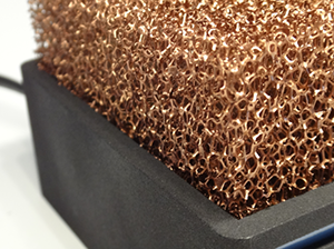
Meet Silent Power (Google translation). It’s a remarkably small and fairly powerful miniature gaming computer being put together by a team in Germany. The specs are pretty good for a completely custom computer: an i7 4785T, GTX 760, 8GB of RAM and a 500GB SSD. Not a terrible machine for something that will eventually sell for about $930 USD, but what really puts this project in the limelight is the innovative cooling system and small size. The entire machine is only 16x10x7 cm, accented with a very interesting “copper foam” heat sink on top. Sounds pretty cool, huh? It does, until you start to think about the implementation a bit. Then it’s a descent into madness and a dark pit of despair.
There are a lot of things that are completely wrong with this project, and in true Hackaday fashion, we’re going to tear this one apart, figuring out why this project will never exist.
The Hardware
The specs for this machine are pretty good; it’s not a slouch by any means. The CPU is an Intel i7 4785T. A pretty good chip, but one with the lowest thermal design power of its generation – 35 Watts – not surprising given that the team behind Silent Power is going for a completely passively cooled product.
The graphics card, however, is not a low power part. The Nvidia GTX 760 is a 170 Watt card, and most certainly not the best choice for a passively cooled system. A better choice would be the GTX 750 Ti: they would get reasonably similar performance with a 60 Watt card. saving them from having to get rid of 110 Watts of heat. If you’ve ever touched a hot 100 Watt light bulb, that’s about how much heat the small performance increase from the GTX 760 to the GTX 750 Ti produces. That’s also the amount of extra heat the innovative copper foam heat sink needs to get rid of because of this one design decision.
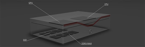
Chip choices and component selection notwithstanding, a much more interesting aspect of this hardware is the form factor. It’s a pretty small enclosure, only 16x10x7 cm. The smallest commonly available motherboard size, Mini-ITX is 17 cm square and obviously wouldn’t fit in the enclosure. Maybe they’re going with a newer, smaller form factor like the Intel NUC? Nope. They’re designing their own integrated system, mounting the GPU and CPU on one board, and the RAM and the Flash chips that make up the SSD on another. There are supposedly a total of three boards in this computer, all separated by expensive, high-speed interconnects.
Just about every graphics card and motherboard you can buy isn’t designed from scratch. Instead, chip companies like Intel, AMD, and Nvidia produce what are called reference designs, which are produced by companies like Asus, Gigabyte, MSI, and EVGA. Yes, there are a few differences in peripheral support, thermal design, and layout, but the basic fact that there are only a handful of designs out there for a specific class of GPU or CPU holds true.
The team at Silent Power is creating a completely new design for their specific choice of CPU and GPU. That’s a tremendous undertaking and something that costs chip manufacturers millions of dollars to produce. The Silent Power team is willing to do all of this for $60,000 USD with a team of three.
Copper Foam
With the hardware design thoroughly debunked, we can move on to the most interesting feature of the Silent Power PC: the heatsink. It’s made of a material called copper foam, an open cell matrix of copper. At first glance, this looks like a decent choice for a heat sink. Copper is extremely thermally conductive, and the huge amount of surface area means there’s a lot of area for heat to radiate out of.
The reality is that this copper foam is a more effective insulator than a conductor of heat.
Heat sink design is no simple matter, and simply by observation of stock heatsinks, a few generalities can be observed. Most heat sinks are made from aluminum, and while the most common explanation for this is the price of copper versus the price of aluminum, that’s not the whole picture. All heat sinks have a property called emissivity, or the effectiveness of a material in emitting thermal radiation. When it comes to the emissivity of heat sinks and radiators, color is important. The radiator in your car is painted black, and the heatsink on your CPU is most likely black anodized aluminum. Copper cannot be anodized and short of artificially oxidizing their copper foam, the Silent Power team can do nothing to improve the efficiency of their chosen material.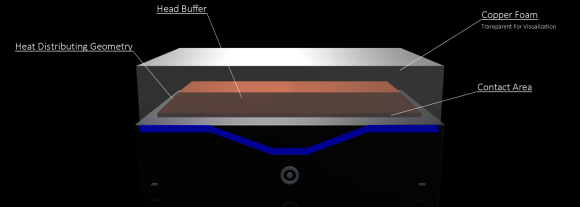
Another consideration in the design of heat sinks is the area of the fins. The fins on every heat sink have something called a ‘boundary layer,’ or an area where heat is transferred from the metal to the air. A lot of time and resources have been dedicated towards calculating the ideal size, shape, and spacing of fins in a heat sink to optimize heat transfer with this boundary layer in mind. A copper foam is not an ideal heat sink. The boundary layer for all the cells in the foam quickly reaches capacity; after that, radiating any more heat is impossible.
This is, quite literally, one of the worst possible heat sinks imaginable.
Previously Found On Indiegogo
While being a crowdfunded project, Silent Power can’t be found on any of the regular sites like Kickstarter or Indiegogo. They’re doing the crowdfunding by themselves, asking everyone to contribute towards production via Paypal. The plan is simple: send some money to them via PayPal, and when they receive €45,000, they’ll start production. If they don’t receive the funds necessary, they’ll refund all of the potential buyers, minus PayPal fees.
Read that last paragraph again and tell me if that’s a reasonable deal. There are things called, ‘investors’ and ‘loans’ that might also work in this situation, doubly so if you’re running a business.
It’s certainly an unorthodox way of raising money for a project, and with a little bit of googling, you quickly find the reason why. Here’s the link to their previous Indiegogo campaign. That campaign was pulled down by the Indiegogo, “‘without warning and justification,” according to the team. If anyone can find a cache of that campaign somewhere, I’ll gladly link to it.
Yesterday, the Silent Power team hit a bit of a snag. Paypal froze their account. Yes, this means all the funds to be used in the development of this project are now locked away, and yes, this means the team has no funds to develop the project further.
That doesn’t mean the Silent Power team is calling it quits just yet: they’re still accepting payments and pre-orders to a frozen Paypal account, ready to start production when their account is unfrozen. The mind reels.
Wrap Up
This is only a cursory assessment of this project, and far from a complete look at the failings of the Silent Power PC. There’s much, much more to talk about here but really only one word that can describe the totality of this project: insane.
I would like to take a few words to point out that this is a critical assessment that comments on the engineering and design of the Silent Power PC, something the rest of the tech blogosphere didn’t seem to manage. In no particular order, here is a list of blogs that have taken an uncritical look at the Silent Power PC, without taking the effort to determine if it is real or not:
- The Verge
- Gizmodo
- Gizmag
- PC World, with the quote, “That’s not to say Silent Power isn’t legit—far from it…”
- Techspot
- Ubergizmo
- Stuff.tv
There is really nothing more for me to say, but there are still dozens of reasons why this project will never see the light of day. Comments welcome below.


While I largely agree, I wanted to point out Clock speeds:
For the intel cpuare lower than normal (less wattage) and the clock speeds and voltages aren’t listed for the GPU, which could be drastically lower (like the GPU miners like to do for increased mining efficiency of coins)
Lower clock speeds mean slower mining.
The only reason you would lower clock speed is to lower temps and wattage. It reduces performance. Period.
And since they claim this is supposed to be a high end gaming PC, why would they clock down a 2.2ghz CPU that already runs at 35 watts? A CPU that is only a few months old and still runs worse than my i5 4670k at stock speed, which is already over a year old, and can also be overclocked twice as much as the CPU which is being used for this “high end” gaming PC.
I think parent poster was talking about undervolting the GPU and CPU, and maybe underclocking the GPU.
FunnyFace’s example was undervolting GPUs in cryptocoin mining, which works because some GPUs are still stable at stock speeds (or higher) at lower-than-stock voltages. On those GPUs, turning the voltage down can maintain the same speed and stability (same performance) but reduce power consumption (improved efficiency).
I don’t know if it’s a rule that if a chip can be overclocked at stock voltage, there’s some room to undervolt it stably at stock speed. But it’s a hypothesis I wouldn’t bet against unless someone’s already tested it. And if you underclock it, I would assume you get more head room to undervolt it as well. I know what they say about assumptions, but it wouldn’t be too difficult to test I guess?
“Copper cannot be anodized and short of artificially oxidizing their copper foam” — Please bother to educate yourself before you contribute some shit like this to the internet hackaday. Anodizing is pretty much DEFINED as artificially oxidizing a metal surface when used in this context, and OF COURSE copper can be anodized to form a layer of black copper oxide with an emissivity coefficient of around ~0.8.
Here’s some more facts for you: you didn’t bother to do ANY KIND of research whatsoever to determine how effective or not a copper foam heatsink could be.
You don’t really seem to comprehend what goes into even designing a circuit board layout when you suggest that a team of three people couldn’t possibly be able to interconnect a few industry standard IC’s.
Please educate yourselves before you shit all over the internet with this drivel again hackaday. Thanks.
Don’t get me wrong, I think this funding campaign is nothing but a scam, but declaring something as completely impossible and against the laws of physics without so much as some back of the napkin math is kinda lame.
Not to mention the even greater point: we don’t live in space. Conduction is far more effective than radiation of heat, so heatsinks and car radiators are rarely painted/anodized black. Painting it black in a car would actually reduce efficiency a long way by insulating the aluminium, and encouraging heat soak from other hotter engine parts like exhausts and turbos (yes, MightyCarMods got it wrong).
speaking of conduction, let me paraphrase a conceptual objection to this heatsink design I vaguely recall reading in the comments section of another website (can’t remember which one):
All the heat that needs to be evacuated by the foam has to enter the foam at the bottom and conduct through the copper strands themselves, from the bottom of the foam to the top. The cross sectional area of this foam doesn’t strike me as being very high, though neither is that of traditional finned radiators. Each may have plenty of surface area to radiate and conduct heat into the air. But which does a better job of spreading the heat throughout it’s own structure first?
For this reason many finned heatsinks employ evaporative heatpipes to move heat from the heatsource to further distant fins on the radiator. Even if a foam heatsink is shown to have improved thermal characteristics to finned heatsinks (which I doubt), I would suspect that a heatpipe+fins heatsink would mop^H^H^H scrub the floor with this thing.
smilr, that is why i’m starting a kickstarter for heat tube foam.
it is just like that the coper foam in this project, but each strand is it’s own heat pipe filled with mercury!
now you have maximum contact area and maximum heat distribution ever archived by mankind! price? i’m kickstarting it, haven’t you read that up there?
Emissivity (thermal radiation) of a heatsink is also irrelevant because air is transparent to the wavelenghts of IR that it emits and will only absorb heat from the heatsink by regular convection (touch), so having a black anodized heatsink actually makes it worse because aluminium or copper oxide is a worse heat conductor than either metals alone. Anodizing does provide some surface roughness which helps with convection, but it doesn’t need to be black.
In general, the emissivity of the heatsink material only matters for the part that you can -see- on the outside, because every other surface won’t be able to radiate any energy -out- of the heatsink, so having a cube shaped mass of foam is just as good as a cube shaped block with some sort of rough dimples.
The air doesn’t need to absorb the IR energy. It just needs to leave the Heatsink.
It’s probably better that the air doesn’t absorb the energy, otherwise that energy would heat the air close to it and slow the conductive energy transfer.
Not saying the project is legit, or not a scam. but I am tired of these hackaday witch hunts that spout as much BS as the crowd funding project hype. There are as many inaccuracies in this article as the crowd funding project. I am disappointed in hackaday. Check in here less and less every week because of crap like this. As the project goes, I doubt they can pull it off, but they might. Some folks might want to send them a few bucks to help them out. That is an individuals decision and responsibility to do the research before ‘investing’. If you want to have an article calling a project a scam, at least have some real test data to back up your attack.
The board design in interesting, specifically for the RAM. A casual search for some DDR3 info turned up this: http://www.polyscope.ch/dlCenter/ps/2010_5/05_10.05.pdf
I’m not sure if the desktop version of the I7’s memory controller can handle SODIMMs (but I’ve seen some strange stuff out there). If it can, having 2 channels could work. There might be something out there in the embedded world they can use (but it would be nice to know if that is the case).
If the SSD is mSATA, that leverages mini PCIe which I’m sure could be routed to a second board without much fuss. Or perhaps they are running the DMI link from the CPU’s IIO to a PCH on the second board. That’s essentially a PCIe connection with some special Intel stuff baked in so it is not impossible to run through a connector.
Getting the NDAs from Intel seems to be the bigger hurdle. But perhaps these guys have experience in this area and figure they can save on having a lawyer dedicated to the task.
They also have platform firmware (AKA, BIOS) to account for. They can’t really go with the UEFI EDK2 because Intel is not in a habit of creating UEFI drivers for their chipset components. They tend to still use a business model where they supply an IBV with documentation and let them write the code to ‘enable; the hardware. Insyde and AMI are your choices for the most part right now. I don’t know what either company is charging for a ‘turnkey’ BIOS right now, but it’s not insignificant. Maybe they can design the board to work with the reverence BIOS used on the customer reference board and get away negotiating royalties with the IBV who provided the reference BIOS IP. That would side step those fees for the initial prototype but I’ll suspect they will run into issues that would require at least some level of source for their system which can get pricey (not to mention the engineers skilled in UEFI BIOS development).
While I don’t think it’s impossible for $60K, I think that is extremely optimistic and I would like to know how they think they can pull off the engineering for that price (let alone the manufacturing).
That is HF design of not only a few industry standard ICs, which is tricky. They would be the first three person team that does something like this within a year with a budget that is only half as high, as the anual licence costs of the necessary cad tools.
It is highly unlikely that a three person team could do the design work of large design teams with more than 100 personyears of experience and education within half the development time of reference board layouts.
In spite of that the article is highly incorrect in terms of the copper foam. The foam is currently in research such as mentioned here as heat pipe filling. It has been around for years and has good cooling performance. The aluminium vs. copper part is totally wrong in terms of physics; The heat conduction of aluminium is about 200 to 250 W/mK, but because of the self passivation of aluminium, the thermal conductivity is going down to about 35 to 40 W/mK. In fact copper has a thermal conductivity of 400 W/mK In terms of radiation the link you (the author of the hackaday post) refers to, the emissivity of oxidised copper is about the same of anodized aluminium.
Additionally the emissivity has a much less influence to the overall cooling performance, which you can also read it your link. Bad research for this article, very bad.
Also I wanted to point out copper foam heatsinks are actually a things, with test results:
http://www.overclockers.com/copper-foam-heatsink/
http://www.overclockers.com/copper-foam-heatsink-ii/
yep, and almost all of them REQUIRE a forced air solution. Convection won’t work well with these due to the high amount of boundary layers and the drag they create. Without a fan, they actually become insulators, trapping heat at their core.
Cooling power lies in the right balance between material density and the surface exposed to air flow. This solution is as bad as it would be a heatsink in the form of a solid cube.
Solid cube might actually be better because of the larger thermal mass.
None of the examples in the links involve passive heat sinks and as was pointed out, once the copper sponge gets clogged with dust, you’re SOL
There is a reason why insulation materials are formed as foam in almost every case.
The two key things to note about those are:
(1) It’s a really, really dense foam (which requires a fan to force air through it). The dense foam helps conduct heat from hot parts to cool parts.
(2) There’s a thin layer of foam over a solid copper base. As a result, the distance that the heat actually needs to travel through the foam is only a few millimetres.
This displays a very realistic understanding of what copper foam is good for. Good for getting heat into a moving airstream due to the large surface area. Very bad for getting heat from one part of itself to another part of itself due to the long and thin connections between different parts.
The Silent Power system has it completely wrong. The layer that’s actually in contact with the CPU/GPU will get nice and toasty, but virtually none of that heat will be conducted up to the top. Instead, the large amount of foam on top is just going to prevent air getting to the places where it’s needed.
The “correct” way to build a passive heatsink is to have lots of big vertical fins reasonably widely separated (allowing convection to pull air through them easily), with heatpipes moving heat from the base to those fins. The old Scythe Orochi heatsink demonstrated the principle nicely – and that still couldn’t handle this much power without a fan on it.
Yeah, the part where they say they’re putting the GPU and CPU on one board rings all kinds of bells.
There’s a reason this hasn’t been done before, it really does cost a shitton of money to do that. More than 45k€, anyway.
Oh and the site isn’t exactly well-built. I’d sure as hell have a nicer design if I were undertaking something so revolutionary.
Doesn’t help that the whois seems to indicate that this was a prebuilt site with no clear owner.
I’m by no means suggesting this project is legit, but in terms of doing something revolutionary, appearances don’t necessarily matter…
http://allaboutstevejobs.com/pics/stevesplaces/garage.php
True. It’s just that transparency is important when asking that much for an unfinished product.
Ever looked at a laptop motherboard? What about some of the newer dual video capable thin clients?
GPU and CPU on a single board.
There are already reference designs available for integrated gpu units, and the 760 is no exception.
Yes, but those companies all have more or less disposable money.
It just seems insane that it can be done by 3 people with such a limited amount of money.
Also, there’s a reason that they were deleted from Indiegogo and are using their own site for the crowdfunder.
Until I see a working design + what the insides look like I’m calling bullshit.
Getting deleted from Indiegogo for fraud is a massive accomplishment. I’m honestly impressed given that half the featured projects on the front page last time were clearly scams or people that don’t know what they’re talking about.
Seriously though, you are going to reference thin clients as an example of proving that an i7 and a top of the line video card can be put on one board, for less than 45,000 (oh wait, that includes fulfilling!)?
That’s crazy.
Having one company building all the components, and it’s still a massive, costly job. Now you want to try it with two big companies (intel and nVidia)?
There’s a reason that laptop manufacturer’s produce a board, and use the same design with some un-attached components for lower cost models. Because even with the volume they do, it’s not cost effective to redesign the board.
I don’t think it’s a smart idea to put the CPU and RAM on different cards, because of the increased distance for the signals to travel and that leads to higher latency. I would have placed the RAM on the underside of the CPU/GPU card, and other parts that require low latency to operate at high speeds.
And copper foam? Sounds expensive, could probably be cheaper to go with a large regular heat sink. Not to mention that most foams are rather bad at conducting heat.
CPU and RAM are on different cards already. Popular memory on a PCB form factor is a DIMM. :) If it is only a few inches, that’s comparable to what the board layout on a PC. Longer than a few inches is silly because of signal quality issues. Long tracks at high frequency has losses and that kind of closing the eye opening.
BTW: Propagation speed ~ 2.0 nS/ft. Seems like DDR3 has latency of 7.5ns range
http://en.wikipedia.org/wiki/CAS_latency
As far as I am concerned, it is no worse than the usual engineering power point of a concept design done by marketing without engineering inputs. Things gets moved a lot during a real design.
That does look like those foams for wiping soldering iron. LOL.
You might want to recheck your physics knowledge there.
Actually it is you that should check your numbers…
BTW Mentor Graphic sells CAD tools.
http://blogs.mentor.com/hyperblog/blog/tag/velocity-of-propagation/
>Here c is the speed of light, μ=1 since we have non-magnetic materials, and εr is the dielectric constant. Typically for FR4, the dielectric constant is ~4.2. There is some variability to that number, but I won’t get into that detail here. Going with that, we can see that Vp on a PCB is about equal to Vp=c/√4….1/2 the speed of light. That was easy math!
>So we know that signals can travel about 6″ per 1ns from this quick and dirty math or invert that and you get 165 ps/inch
The issue with moving components onto separate PCBs isn’t latency – light really is pretty fast – it’s parasitic capacitance and inductance, which leads to slower rise and fall times.
I’m not sure it’s latency, as such at this level – I think it’s more to do with the resonant frequency of the traces, capacitance, cross talk and whether or not the damn things act as an antenna. Either which way, if Nvidia’s reference design has the memory laid out radially around the GPU, I think keeping those traces short and all the same length is a *very* big deal.
copper foam? Sounds expensive.
Brillo scouring pad. They are $1 each or so.
Somehow I’m inspired to clean my soldering iron tips using this technology ?!?!
Let alone the “copper foam” idea does not stand up to thermal transfer calculations.
That is a pad to clean your soldering iron tip with. I prefer cellulose sponges personally.
So how did they manage to put their hand on Intel yellow and red books to implement the CPU and north bridge?
This, among other things mentioned.
A development and support contract for AMI Aptio costs more than they’re asking for the campaign, not including the per unit licenses.
oh CMON, Im sure they can design 8-12 layer PCB on the first try!
We routinely do 20+ layers boards and rel 0 protos works to a certain extend. Not much of a challenge if you have done the SI/timing/thermal/mechanical modeling and simulations stuff upfront.
more layers makes a board easier to lay out, not harder.
A board like this is not rocket science. Any competent layout person can get such a board right first go. BTW, the number of layers doesn’t matter much. In fact more layers usually makes a PCB layout job easier.
its not easier when 12 layers is what you need at a minimum to route 256 pins at 6GHz (memory interface for GPU). Even big prosperous laptop manufacturers with wads of cache (DELL, not taiwan ones) avoid designing in gpu right on the same motherboard and use MXM cards. Shit, even Apple, the maybach of computer design, use MXM on imacs instead of routing desktop gpus on their own boards.
and its certainly not cheap
lets say three spins or 12 layer prototype pcb, how much of their budget is that? 1/3?1/4? maybe even 1/2 ;)
Nothing is easy when you try to implement chips without mfg support, and I highly doubt anyone at nvidia or intel will talk to them.
Brillo Pads are steel. Color is not indicative of material.
http://en.wikipedia.org/wiki/Brillo_Pad
Umm.. Brillo pad? Ok.. Project for you.. Take a Brillo pad and touch a 9v battery to it….
“Chore Boy Ultimate Copper Scrubbers have the cleaning power of steel wool. The Copper Scrubber is machine knit of pure copper strands that create a soft feel scrubber. This pad will not rust or splinter.”
I was using Brillo Pad as a genericized trademark. Not all of them are copper based.
Looks cool though!
20K each and laughing all the way to the bank.
i don’t know really the copper foam could work in theory if you had a decent enough airflow through it, but as a passive cooler no way. this thing is gonna heat up like a brick..
A heat sink like this, made of foam, as shown, would have a steep thermal profile because the cell sizes and cell wall thicknesses seem to be the same.
Ideally if they could make a foam with thick walls close to the heat source, getting thinner as they moved away it might be workable.
A better way is to make wedge shaped flat copper sheets that would be ~2 MM at the heat source and tapering to 0.2 mm at ~~2 inches.
This would be the best way from solid copper. Thermal heat pipes = better = $$
there has to be solid copper somewhere, otherwise how would they mount/secure the ICs to the foam? all the examples I’ve found used aluminum or copper base attached to the foam: http://www.overclockers.com/copper-foam-heatsink-ii/
I would also think that some sort of moving air convection tunnel would need to be engineered into the foam. For instance, intake vents underneath tunneling upwards so a venturi is created by the rising heat. Passive radiation is only good if there is a thermal mass of air flowing across the vents.
I really like the comic sans on the site. It just reeks serious professionalism.
The copper foam should work pretty well, i think, if actively cooled. If not it’s just an insulator brick.
“if actively cooled” being the key component.
You could add a fan to get more cooling, so much for the silent part, a filter to block dust particles from clogging the “copper pad”. That does away with the “look”. You could use electro-deposition and slowly raise the copper pad out of the electrolyte to deposit more copper at the base of the pad. That will also cut down on the flow through the pad. You could use a fluid cooled system and pump the coolant through the pad.
But it all comes down to the fact that you’ll give up the form factor and the silent operation and be back among the rest of the pack. I’d rather invest in potato salad.
How did they raise 33k?
The problem with the *slowly* part which isn’t really good for volume production. For a production heat sink, you want to extruded it (like a pasta maker) or cast or forge it etc.
No matter what you do to the heat sink, to dissipate that amount of heat requires a *minimum* amount of air flow i.e. volume of air / second. The heat is transfered from the heat sink to heat up the air by a delta T. (Radiation is a small fraction and that’s not even worth included for low temperature.)
So convection alone won’t have the air volume. A really bad design like the sponge ™
would trap a warm layer of air.
And like [Bill Jackson] said, the profile isn’t optimal. So you would need even more air flow. May be they are hiding a Dyson bladeless fan inside. :P
this is ridiculous. and this is way. copper foam is a bad idea because the airflow to dissipate the heat would be very restricted. that’s why you see copper fins in coolers. not foam. multi billion dollars in research regarding chip cooling and now they say copper foam? lol.
but actually this could work in a slight more bigger case. with watercooling with a 180 low profile rad and low profile 120mm fans would work. in fact I’ve one as my hdpc in my living room.
nothing to see here expect for the fact that there’s some morons that believe it’s true…
No copper foam could be an excellent heatsink however I don’t see how it would be realistic to mass produce. The reason is because even with the increased surface area one have to transfer the heat to the surface to make use of it. So there have to be a complex tree-type heat spreading design embedded into the foam for it to work – and while I can see some ways to create such a structure for a one-off project (3D printing a mold and use centrifugal casting) the mold have to be destroyed for every produced heatsink.
It could perhaps be possible to create the heat spreading structure separately from the foam part and still get a single part in the end but it would still cost a lot per heatsink.
>copper foam could be an excellent heatsink
Not really, no.
You don’t want to trap the heat, you want to dissipate it, and a copper foam would have a maze of tunnels for the heat to get trapped in.
as it was said and proven by a thing called laws of physics (you might want check that out) copper foam is shit.
as for mass producing it, it’s really really easy. as easy as aluminium or steel foam. kinda like scrubbing pads for washing that are dirty cheap.
there’s industrial manufacturing processes for that since at least 1 century ago.
NOTHING to see here.
As soon as i heard they’re using paypal for ‘crowd sourcing’ i thought to myself it’s going to get locked. I continued reading and sure enough it’s been locked. Ugh how stupid are they?
Also Paypal refunds are in full, including any fees charged. So I don’t know why they said ‘excluding paypal fees’ .
sounds like a job for Bitcoin with full escrow!
PayPal locking accounts is standard practice for such projects that suddenly get a large influx of orders. Their system will automatically flag such accounts as suspicious.
PayPal locked my own legitimate crowd funding campaign through Pozible. Took a day or two to explain and get it reactivated.
I don’t know where the facts for this were pulled from, but car radiators aren’t painted black. I think the writer is *MAYBE* talking about old copper radiator cores, which were painted as a corrosion inhibitor, but that absolutely nothing to do with heat transfer. Aluminum radiators have replaced copper decades ago as they’re cheaper to manufacture and more consistent in length of life, AL being far more corrosion resistant than CU. Aluminum radiators typically have black plastic end tanks, but they’re never painted black, as there is simply no need for it.
I have never ever ever seen a painted radiator
Go to a junkyard some time. Many radiators have black painted aluminum fins.
No irradiators have “painted” black fins. Many are black anodized, though.
I was thinking the same; seen a few PC-watercooling radiators that were black but never a car radiator. Also never seen a black-anodized CPU heatsink, just bare metal, except on really old stuff like the P2.
they do make aluminum foam. maybe that would be better than copper.
For what purpose? Not for heat transfer surely.
1. Unless the heat sink is in a vacuum the majority of cooling is from conduction not radiation so the color is not important.
2. The boundary layer does not help cool a heat sink. It is an area of sluggish airflow actually acts as an insulator. You want a turbulent flow over the fins of the radiator so that you get maximum heat transfer.
Frankly a copper sponge would make a good heatsink in theory. I question if it has enough conductivity between the heat spreader of the CPU and the sponge matrix to work.
Turbulance = Noise.
If it’s a passive heatsink then a heatsink which generates turbulence is going to inhibit overall flow speed. Probably more effective not to inhibit convection.
Absolutely agree on conduction vs radiation.
Honestly though, foam would need to be specially designed for use as a heat sink. You’d want something with good contact, to pull heat from the chip, and then decent mass to conduct it away, before breaking down into the small surface areas to conduct it into the air.
There’s a black anodized radiator as part of a liquid cooling loop on my PC right now, my ford explorer has a black anodized radiator, the humvees and caimans I drove in the military both had black PAINTED radiators. The generators and cooling units on the FDC command humvees I used to operate all had black CARC paint on their radiators, and I’ve even seen green CARC on some radiators. I could continue, but you get the point by now. Just because your particular car does not have a black radiator does not mean all cars/radiators in general are the same.
Ya ya sure Hackaday, you guys showed that bullshit “lithium ion” battery project that can recharge in a supposed 30 seconds. Say whatever you want about this, you are just as guilty of LACKING CRITICAL ANALYSIS OF A PRODUCT.
(http://hackaday.com/2014/07/17/a-lithium-ion-supercapacitor-battery/)
This project is quite silly. I will give you that.
You didn’t read the update.
I don’t think the readers like HaD spot lighting Scam funder articles. May be just my opinion or that 100+ comments don’t count?
HaD staff might like it because of the page view, but don’t think the advertizers would like to associate with scams and pseudo-science stuff.
Higher emissivity of thermal radiation also means much higher absorption of the same. Any emitted infrared energy that restrikes the heatsink is efficiently reabsorbed. Wouldn’t be much advantage to anodizing a foam heatsink, where the majority of the surface area doesn’t have clear line-of-sight to the outside. Even some traditional extruded heatsinks with parallel fins suffer heavily from restrike.
As for Prandtl’s boundary layer, that describes the property of a fluid (gas or liquid) to form a layer on the surface of a solid, that moves much slower than the gas around it. Optimal heat transfer occurs if a steady supply of new gas molecules directly come into contact with the metal, which this slower-moving layer impedes.
This layer cannot be completely eliminated, but it can be reduced by flow. But a smooth flow mostly just slides across the layer, without breaking it up much. TURBULENT flow is much more effective.
Using foam for a passive heatsink would impede internal convective flow, but the flow that occurred would be more turbulent, due to all the changes in direction of flow. So I wonder if this foam idea might actually work – IF the heat input was from one or more horizontal edges, and there is an otherwise unimpeded convective air path from bottom to top. Which is NOT the case here, as the bottom is the heat input, and so is blocked off.
I saw an old film as a child in which a grounded piece of metal, glowing red hot, was cooled in SECONDS simply by pointing the output needle of an ionizer at it. It was explained that the ionized air molecules, being strongly attracted to the metal, punched right through the boundary layer as if it weren’t there at all; something that can’t be accomplished with any amount of normal air flow. Sounds feasible, but strangely, I have not seen this replicated or mentioned anywhere since. Not even in the ionic cooler builds featured here – in all those, the charge is stripped by a grounded grid prior to hitting the real target, leaving only traditional mechanical airflow. So maybe, despite all the knowledge we have about heatsinks, something new and interesting might come along, or something old remembered…
HaD went a case mod type of article for the ionic wind style cooling a while back.
Also this technical brief
http://www.electronics-cooling.com/2012/03/ionic-winds-a-new-frontier-for-air-cooling/
Lets face it, largely the only crowdfunded stuff these days I see on here is “what wacky project will we debunk this time?”…..so after the stunningly stupid runaway circus that was Potato salad, at 55k backes over 10$ goal……….every time you guys want to write “most insane/crazy/weird/etc” crowdfunding……think if it beats potato salad.
Problem is hardware development takes money. CAD (Simulation, layout, thermal, mechanical tool) licenses cost money and time. There is inventory cost for parts, material, set up cost for making a small run PCB assembly, then you have to rent test equipment for testing out the boards/debugging and probably also need to license/customize the BIOS, get lab certifications for FCC/UL etc.
Now this is just the basic engineering cost. For a big company, this stuff is sometimes spread over 2 or 3 departments to do the work and then the infrastructures such as IT, marketing, purchasing, accounting etc.
For an actual product, may be the number should be multiply by a factor of 10 to be realistic (and that’s cheap). Could be the right amount in China, but this scam isn’t in China.
Wow. You have no sense of humor, tekkieneet. Comin off a lil douchy in this thread…just sayin.
The web site misses a proper Impressum (there IS ONE, but it is vastly incomplete). The web site claims that a 100% money loss is possible (even though they say they are forced by law to write that, it only has to be written if it is TRUE, so …). If you decide to believe what is written in the Impressum, then this “company” has NO protection scheme whatsoever, you might want to try to get a hold on the two young boys in the “about” and the girl, but with the new insolvency laws just installed in Germany, good luck with getting anything but a cold smile.
There is no word about the (legally required) waste disposal “memberships” (not sure of the correct expression here, sorry, I am only German).
No CE?. EMV? ROHS? Just to name a few of the required confirmations, none of which are presented.
If someone wanted to do something like this for real, the first thing would be to found a company with a proper financial protection (for both the company AND the customer). Then have a complete website with all legal data available. Then NEVER EVER use a non-trustworthy service like Paypal (hey, Paypal is NOT A BANK, so the European financial protection system of up to 100000 Euro does not apply).
This stunt stinks. From both the head and the toe. Even if the kids there mean it seriously, in my eyes they are doing everything wrong that one could do wrong with such an endeavor.
I’m not sure about Paypal not being a bank in the European Union as it have a Luxembourg Banking License and have been operating as a Luxembourg bank from 2007 in Europe.
However, I don’t think banking rules of Germany would apply to anywhere else in the world. In the U.S., PayPal is considered a money transmitter and as such, offers no protections to the consumer whatsoever.
German insolvency laws don’t affect debt resulting from crimes like fraud. So people can get away with it…
While I agree with the impracticality of the copper foam passive heatsink, I don’t think that the custom motherboard would be a show-stopping issue. Look at all of the “Ultrabook”-style laptops on the market today; they each have a custom motherboard with CPU, chipset, and RAM soldered to a single logic board. Routing high-speed multilayer boards is a solved problem, albeit a difficult one. Putting RAM and SSD on separate boards is something that we routinely do in PCs, in DIMMs and SATA SSDs, respectively. Also, bunnie’s Novena laptop also uses a custom board with high-speed components. He routed a 1.4 GHz SoC, DDR3 RAM, and an FPGA. So, it is possible for an individual to route a custom board with high-speed lines in a similar range to what this team is purported to have done.
Bunnie Huang is a qualified electrical engeneer. He as a P.H.D. an we know where he got it. What are the credentials of these 3 persons? In their short “bio” no one talk about is education background…
And their copper foam really look like a scrub pad! which is not foam at all but wire mesh.
Even before the PHD, he is a full fledged elite hacker. Look at some of the earlier stuff he built on the web page.
Let’s say there is one un-named web celebrity that came out of that same school that I wouldn’t qualify as a junior engineer.
Dissipating this much heat passively is no small task. The Re:load Pro has the biggest heatsink I could reasonably fit on the back, and is still only capable of about 35 watts under reasonable conditions. Airflow makes an _enormous_ difference.
“With the hardware design thoroughly debunked”
Not really. You just pointed at the big boys and said “look they spend a lot of money on this!”
Not saying thats wrong, but I think for the logic to be complete you need to say *why* its so costly, and specifically why it cant be done cheaper / with a smaller team.
Because when i want an i7 machine i dont want no pesky cheap, silent, easy to clean fans! i want my machine to look like something used to clean the stove!
I’ve got a better word for what they’re doing than “insane”……
FRAUD!
If you are already surprised about some tech blogs spreading this “news”, then you will be definitely shocked that various prestigious commercial journals here in Germany also report on their websites about this silly project and thereby somehow advertize it.
I could name at least 10 further reasons why this project definitely is a fraud. However, as some people here doubt the impossibility of the motherboard design:
Even if they could build such a tiny board with both CPU and GPU (and, necessarily, graphics RAM) on it, at least they would fail connecting the other boards to the “main mainboard”. There is a reason that mainboard manufacturers put the RAM slots as close as possible to the CPU socket. Otherwise, reasonable latencies cannot be achieved. And doing so with pluggable interconnects is just insane. This is exactly why you do not connect your RAM the same way as you do with your HD / SSD.
Also for engineering reasons:
Having to route a very wide parallel bus a long distance eats up your board space as you can’t put anything beyond simple caps/terminating resistor on top of that. Dead space = waste of board real estate.
Also connectors degrades signals. DIMM socket is one thing that is already accounted for in a reference design, but if you add more connectors you have less eye opening (aka signal issues). Long track also degrades the signal (especially the high frequency), once again leading to less eye opening.
Extra connector cost money/reliability issues.
Having said that, what of the interconnect is where your expects the DIMM except it is to a daughtercard that houses the memory chip directly, so your time of flight isn’t that much different? (Also vendor lock in , specialized expensive memory etc too)
In response to the press coverage “silentpowerpc” put the logos of all publications on their page, to make themselves look more legit. This smells even more now.
Interesting article. While colour does affect an objects ability to either act as a radiator or an absorber of heat, I just wonder about the practicalities of “copper foam” as a heatsink. How easy will it be easy to clean the device once it becomes caked with dust and other heat convected debris?
put it in a dish washer along with the other $1 scrubbing pads?
Someone who did an actualy experiement doesn’t seem to think that metal foam heat sinks totally suck.
http://www.academia.edu/5714360/Experimental_Investigation_on_Pressure_Drop_and_Heat_Transfer_Characteristics_of_Copper_Metal_Foam_Heat_Sink
It’s downright dishonest for you to present that as representative of the passively cooled metal foam found in the Silent Power project. This is from your link:
Sounds a lot like using a fan to blow air across a copper foam heat sink, right? The crowdfunded campaign uses no fans, and is passively cooled.
It’s downright dishonest for me to present a link showing experimental results that show metal foam heat sinks can perform on par with fin heat sinks when the only proof/evidence/experimentation/calculation you’ve used in your assertion that they are using the “worst heat sink ever” is ……? What exactly? I didn’t make any claims that the linked paper showed this heatsink is feasible.
Wouldn’t it at least be somewhat reasonable that if they perform similarly to finned heat sinks in the presence of air flow, they might perform similarly in no-airflow? Surely, they aren’t the “worst heat sink ever”.
http://electronicpackaging.asmedigitalcollection.asme.org/article.aspx?articleid=1408392
Finned vs foamed Buoyancy-Induced Convection
“However, when compared to commercially available heat sinks of similar dimensions, the enhancement is found to be marginal.”
“This is, quite literally, one of the worst possible heat sinks imaginable.”
As a longtime reader of Hackaday, I’m actually very disappointed in the author’s complete lack of any background research on the performance of metal foam heat sinks. Literally 15 seconds of googling (‘metal foam heat sink performance’) will land you some respectable journal articles, even ones that you can read in full for free(!), that report results showing foam and finned heat sinks are basically equivalent.
Sure, maybe this kickstarter is sketchy, but at least do a little research making a bunch of claims.
I assure you, I could find no references to passively cooled metal foam heat sinks. If you’re able to find any references, please send them my way.
http://electronicpackaging.asmedigitalcollection.asme.org/article.aspx?articleid=1408392
I did exactly just that: https://encrypted.google.com/search?q=metal+foam+heat+sink+performance
google say: About 444,000 results
Hmmm… the second entry (first is a pay-walled IEEE paper) is: http://docs.lib.purdue.edu/cgi/viewcontent.cgi?article=2149&context=iracc
This paper starts off with a review of several other studies. They summarized one study [8] which looked at a particular high-porosity open-cell metal foam: “Experimental results showed that natural convection is significant in metal foams due to the high porosity and inter-connected open cells.” The summary of another study [7], which looked at forced convection: “Experimental results showed that the transport enhancing effect of thermal dispersion is extremely low with foam-air combinations, but for foam-water combinations it can be very high.”
Not what I intuitively expected…
[7] Calmidi, V.V., and Mahajan, R.L., Forced convection in high porosity metal foams, J. Heat Transfer, vol.122, pp.557–565, 2000.
[8] Zhao, C.Y., Lu, T.J., and Hodson, H.P., Natural convection in metal foams with open cells, Int. J. Heat Mass Transfer, vol.48, pp.2452-2463, 2005.
I agree on your opinion, HAD is generally interesting content but occasionally some of this sort of personal opinion slips through.
Passive cooling is used in many applications so to say it is the worst possible heat sink is false. ‘Literally’ being the worst possibly heatsink would be a layer of insulation.
The evidence given is some bullshit about boundary layers which is also false as convection of heat has been used extensively with passive heatsinks with plenty of success regardless of this claim.
If anyone actually looked at ANY heat transfer calculations for this sort of application it is clear that the heat dissipation is proportional to the surface area of the heatsink regardless of being passive or actively cooled and it is true that the copper foam maximises surface area for a given volume.
This paper is closer to what they are using:
http://electronicpackaging.asmedigitalcollection.asme.org/article.aspx?articleid=1409652&journalid=118
However one major issue that all these papers seem to overlook is the ‘dust bunny’ scenario, any airflow through the sponge is going to introduce dust and that is going to fairly well bugger up the air flow in a matter of a few months.
So even if they do manage to get this working, the question is going to be more about long term survivability of the electronic device.
i like the idea of this but the execution is all wrong.
make it single board. get rid of the connectors.
use a more conventional high fin count sink like the ones used on laptops.
use a gpu with a better tdp.
use ion airflow generator.
No, don’t use ion anything generators on a PC motherboard!
its not impossible to isolate the ion generator from the rest of the hardware. just ground the sink.
While I agree with your overall conclusions I think that your claim about copper not being able to be converted to an ideal radiative surface is false. See http://blogs.rsc.org/ce/2013/01/14/december-crystal-clear-a-crystal-snowflake/ for one example of how a copper surface can be given a fractal oxide surface that will radiate red and infra-red very effectively. I suspect that the foam block geometry is far from ideal too and that it could benefit significantly from optimisation (what does time on a super-computer cost these days?).
And not only that, but the implication that black annodized aluminum is an effective radiator is questionable – I read a comment on reddit where they described having to paint an aluminum radiator black because black annodizing wouldn’t handle infrared effectively. Most of the guys in the electronics/amateur radio subreddits know their shit.
umm.. They might know about electronics but a car radiator does not cool by radiation. It cools by conduction and convection. It is all about conduction.
Seems dicey, but your debunking could use some work.
Most of the aluminum heat sinks I see these days are raw aluminum, not black anodized.
Also, boundary layers aren’t going to have an impact on radiative heat loss, not so good for convection on the other hand.
A 750ti isn’t similar performance to a 760, the 760 has twice the performance which is massive in the PC world.
Where was the debunking here on the Solar Roads project? Ten minutes on that project shows up half a dozen impossibilities, and another ten, probably a half dozen more. The concept is borderline moronic, but all it got from Hackaday was “It doesn’t seem impossible…”
http://hackaday.com/?s=solar+roadways
Copper “foam” heatsink solutions are real and usable in niche apps, but they are usually designed for forced air cooling system (some are used in solar air heaters for example) and as you say likely won’t be very efficient at all in free air. Would be interesting to do some free air tests though, but in comparison to what?, same volume regular finned heatsink? Same weight regular heatsink?
and the bonding of the foam will have quite a large effect too.
The whole “Foam” descriptor is false. The picture shown is of a copper lattice. A foam would have some walls to the bubbles blown. BTW, there are open cell foams and closed cell foams – open cell is more like the lattice pictured, although open foams still have a lot of cells walls, they just have enough popped walls that there is a path for gas/liquid through them. A closed cell foam is a barrier to gas/liquid and is the best type for insulation.
The tradeoff is density. A foam that is 1-2 pounds per cubic foot, has lots of void areas and popped cells walls. As the density increases the foam gets more and more closed, and about 10-15 pounds per cubic foot consists of gas bubbles fully surrounded by plastic. Pure solid plastic varies from 60-75 pounds per cubic foot with zero bubbles.
Melted copper does not form a film. If you bubble air through melted copper the surface bubbles collapse immediately, so a foam is hard to make, even lattices as pictured are hard to make from the melt. They can be made from fine copper wire laid in a pattern and expanded, or the woven brillo pad method. I have read that metals foam can be made in zero G more easily and by rapid expansion into a vacuum.
A search show these methods http://bit.ly/1skSHRO
and these images http://bit.ly/1udsRig
Some good heat exchanger pics here: http://www.ergaerospace.com/project-gallery.htm
While maybe not technically correct, a lot of manufacturers call it a ‘foam’.
“The most insane crowd funding campaign ever” is, by a country mile, Solar Roadways. Nothing will come close for quite some time.
To be fair, that was crowdfunding on a crowdfunding site. This is crowdfunding with a frozen Paypal account.
It’s shit like this that makes me want to try and launch a Gluten Free Fedora, or something…. People are fucking idiots.
As a reader of gizmag, it’s Gizmag, not Gismag.
although passive cooling to save a few amps that a fan would cost does not seem to be that productive, if you used that heat dissipating stuff on the heat shields of the space shuttle and enough fins, it would probably work. But the question would be why? More compact, less moving parts, more consistency with fewer parts to clog up or break?
Although I like the idea of a mesh of copper, (it is a really high amount of surface area), and would make sense to disrupt air flow and add to intersection of air and metal, (although not an expert in heat flow aerodynamics), it would seem to be like using the individual strand of hair approach to cooling, where an object has many strands, not many plates, and each strand is curly to intersect with more air flow.
And makes for good paintings also.
See: Di Vinci painting as student.
See: Medusa
And could avoid ‘head set on fire’ effect.
Robert Eastwood
The heat shields of the Space Shuttle are pure insulators, that’s the point of them. Previous missions used “ablative” shields where enough heat caused the shield material to flake and fall off, taking heat with it. But with the design of the Shuttle, the insulators cover the whole outer surface of the thing, glued to the frame, and of course, they’re meant to be re-usable.
Unfortunately having to check every single tile to the constraints necessary meant that the re-usable heat shield would take weeks to check and be ready for flight again. Same thing with the engines etc, basically the necessary safety limits meant the reusability was at the expense of practicality and cost, they’d have been better sticking with disposable rockets. Which they now do.
There’s some other Shuttle problems too, the original design would’ve been a lot smarter and more efficient, certainly not needing the dangerous solid boosters. But the Air Force decided, at some too-late point in design, that the maximum cargo capacity be increased enough for some “things” they wanted launched. Since they were paying a lot towards it, many great designs ended up crashing through other great designs and the whole thing was a bit of a mess. Still beautiful for what they achieved, but nothing compared to what they’d have if NASA had any respect and proper funding. Vs new and exciting ways of massacring brown people without having to leave your office chair.
they should get inspiration from the apple macintosh g4 cube
it is passived cooled
their is a version with dual processor
it works :)
(it even has a classical non ssd hard drive which makes more heat)
and sorry for the grammar faults :)
Let me know when you start a kickstarter campaign to pay for a respected engineer (or engineers – but most perhaps best with a standardized process so that following and evaluating results is on a more level playing field) to do a walk through of kickstarter campaigns in a way for us to learn what is real versus risky. I’d contribute.
Makes the potato salad kick starter look legit.
They should be held criminally responsible for this shit. It is complete bull shit.
this specific implementation of a lattice/woven porous media heat sink may be a terrible idea, but the author of the article and most of the comments here fail to understand why. One can, and many do, in fact design bad ass heat exchangers out of these materials. For this specific discussion surface emmisivity, heat trapping, and just about every (I didn’t read them all) application of boundary layer analysis is non sense.
Most here should probably stop pretending they have a firm grasp on radiation, natural convection, boundary layers, turbulence, fins, heat exchanger design, and probably basic thermal physics, etc. But I get it, you read wikipedia and you’re know it all nerd gods; so thumbs for mastering a suite of subjects most undergraduate majors in the field do not. humility is for chumps
I think the idea is, these foams are quite good, but not at passively cooling to free air.
In that case, they’re bad. Right?
Two companies have already created one of these. It’s called a playstation 4 and an xbox one. And they are pretty cheap…
Hmm. Doesn’t seem plausible. But I wonder about one thing: Do you guys think it would be possible to put all the goodies into a thermally conducting liquid, which is not electrically conductive (such as mineral oil), then put this into a metal box, then wrap it around with a copper pipe and use adiabatic effect to cool it down? Would double as dehumidifier.
” If you’ve ever touched a hot 100 Watt light bulb, that’s about how much heat the small performance increase from the GTX 760 to the GTX 750 Ti produces.”
That’s not quite how it works
“and the heatsink on your CPU is most likely black anodized aluminum”
On what planet is this?
And btw, don’t they use copper foam in some server systems and space missions?
You ask us to be critical and then take such shortcuts? Not smart maybe?