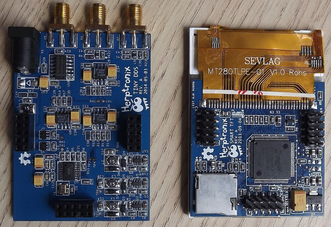
[Herp] just shared a nice 1MHz Arbitrary Waveform Generator (right click -> translate to English as google translation links don’t work) with a well designed user interface. His platform is based around a PIC32, a TFT module with its touchscreen and the 75MHz AD9834 Direct Digital Synthesizer (DDS). Of course the latter could generate signals with frequencies up to 37.5MHz… but that’s only if two output points are good enough for you.
As you can see in the video embedded below, the ‘tiny dds’ can generate many different kinds of periodic signals and even ones that are directly drawn on the touchscreen. The offset and signal amplitude can be adjusted using several operational amplifiers after the DDS ouput and a separate SMA TTL output is available to use a PIC32 PWM signal. The platform can read WAV audio files stored on microSD cards and also has an analog input for signal monitoring. Follow us after the break for the video.


Really nice project. Love the design. Even thought, I would have made it operable by hand. A DDS is part of my to-do-list and I will definitely use some of this for it =)
(As a semi-native speaker I would say that there aren’t any important infos in the video that you couldn’t figure out by looking at the image)
The closed captions are good (i.e. not machine-transcribed and -translated).
Arg, should have activated the youtube subtitles… my fault, sry ^^ Thought there weren’t any in English…
Abritrary waveforms are my favorite kind :D
Hate to point out that it is not arbitrary waveform as that would require an external waveform table in RAM of some sort. It is just a regular function generator (with DDS).
The DDS being used that can only generate triangular (it fed the ROM address to DAC) or sinewave (ROM address to internal ROM to DAC).
The arbitrary waveform is generated directly by the µC, not the DDS-Chip. Look at the video around 5:40.
Wait is it arbitrary and DDS at 1mhz? or is only the DDS at 1mhz or only the arb?
What none else noticed the misspelled title?
Or maybe nobody cares?
noticed but have already given up, perhaps?
Once pointed out, posts here are generally corrected if the mistake is in the body, but if the mistake was in the title, they are not. I’m guessing this is due to the fact that correcting a title would result in many broken links, since the article url is a reflection of the title…
This is really quite an impressive project, and I realize the guy had already built his own LCD GUI controller and wanted to use it, but personally, I’d rather have an AWG controlled through an OpenWRT board or something like that. Just have it serve up an HTML/JS app that posts back commands to the router. It would be easier to add features/hack/debug, probably quite a bit cheaper, there’s no awful stylus to lose, and it can be controlled from any phone or computer on the network.
I would agree with the Stylus part if he wasn’t using a regular old mechanical pencil.
The two output points really isn’t the case. Yes, there are two samples at fs/2, but the anti-aliasing filter reconstructs that into an analog sinusoid.
This project lets you get 8 channels DDS Pulse Density Modulation from a Parallax Propeller 1 chip: http://obex.parallax.com/object/688
There’s talk about a clock skew over at the Parallax public forum, but it’s something which sounds like it is universal. Might be fixed by investing in a new crystal, maybe, if there is no way to add inertia to the PLL. For audio apparently this makes a 12-bit DAC near-redundant with the Propeller!
Of course with DDS you should have yourself a nice filter too. In hobby circles everybody seems to use low-pass RC filters but there is a thing called linear, or active filters too. The best of the bunch is a Finite Impulse Response filter if memory serves me right. FIR filters are implemented in both analog and digital with the same theoretical framework, and I definitely don’t remember how that was done. Something about ellipses and I/Q?