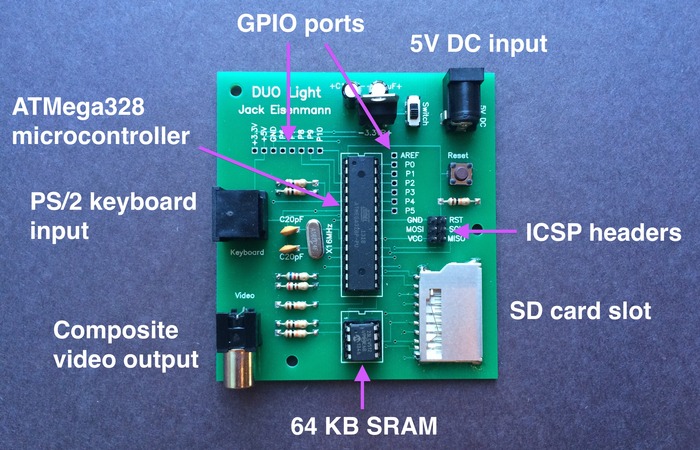
The hardware can’t get much simpler. The DUO Light uses an ATmega328 (commonly found on Arduino boards) along with an external SRAM chip to provide a low-level computer programming experience that will suit those new to programming and some more experienced tinkerers.
At the time of writing the modest Kickstarter goal of $1100 was just $18 shy of success. We’d wager that this is partly due to the availability of so much support material on [Jack’s] website. (fyi- a lot of the links on that page are zip files)
The SD card slot accepts a FAT16 card with byte code for the programs. The available Psuedo C compiler, and assembler let you pick your poison, or you can simply dig into the byte code directly. We didn’t see a schematic, but the firmware and BOM are both available. You should be able to easily figure out connections from those.
We’ve been a fan of [Jack’s] work for quite some time. His TTL computer and 16-core ATmega-based offerings are sure to delight, even if you remember seeing them go by the first time. This isn’t his first stab at educational models either. Though we still found his logic chip computer a bit daunting.


I appreciate the effort made! By now the project is already funded, so good luck for the creator, and let me have fun with my own Duo Light :)
He says it’s $15, but it’s actually $22?!?
The $22 price includes shipping fees (within the US), Kickstarter fees, and Amazon fees.
So what was the point of even mentioning the $15?
A bazillion vga monitors are out in the wild, half a bazillion hdmi monitors – but who has a composite monitor? Unless composite monitors are as cheap as this board – I don’t see it being a good “learning system”.
Who doesn’t have a composite monitor? My 60″ Sharp TV has a composite input. I can’t imagine that it is unique in that respect. In fact, I know it’s not because my home theater amp has composite inputs also. Neither device is more than 2 years old, so composite is not a dead technology despite its age.
If a composite monitor cannot be found, modulators are cheap and readily available.
NTSC also takes fewer pins to drive than VGA (two vs three).
Also the lowest “real VGA” resolution doubles the vertical resolution and halves the horizontal resolution … and it’s already the rather unfavorable on-screen width of 85 or 102 pixels (I can’t tell how many nominal pixels are lost between characters).
What I don’t personally understand is why he says PAL users have to get a NTSC-to-PAL converter … rather than just changing the constant of 263 scanlines to 313.
I do not have a PAL television, so unfortunately I cannot create (test) PAL firmware. However, I am working with a couple of people in Europe to develop PAL signal generation. If successful, I will offer the modified firmware as an option to customers.
Well – I suspect that he is using something akin to the TVOut library (for the Arduino) – basically bit-banging a composite signal. While I do know that people have been successful outputting VGA on the ATMega328, you have to sacrifice even more pins, plus there isn’t much room for anything other code on the device – or you have to add an extra IC to do the heavy lifting (like the Uzebox uses).
As far as “who has a composite monitor”? Well – I do, and I bet many others do as well. Plus there’s always those low-cost vehicle backup camera monitors that can be used (most of them take composite inputs). You can also still buy composite to RF adapters (we’ll never be rid of the coax connector, it seems).
My question to you would be: Why don’t you have a composite monitor (or something that accepts it)? Surely you have a junk pile like every other hardware geek, right? I’m sure if you dug deep enough, one’s lurking in it somewhere. If not, then you owe it to yourself to get one!
Sure I have a monitor with composite inputs, I’m just saying it’s a bad choice to saddle a board designed for beginners. And I doubt most beginners will be willing to plug in a $20 card into their 60inch flat panel tv or expensive AV receiver.
My main IPS computer monitor only has digital, VGA inputs,and no composite/component/s-video inputs. I bought a cheapo TV as a 2nd monitor specifically to get component/svideo/composite and TV tuner for watching OTA TV with an indoor antenna.
The TV suffers from too much crappy processing,on the HDMI input, so I ended up having to use VGA input for my computer.
Impressive work on the bytecode interpreter.
It would be nice to see the hardware design; I couldn’t find a schematic or gerbers.
bytecode interpreters are easy. writing a toolchain for it, thats hard.
I just posted the PCB file on my website:
http://www.ostracodfiles.com/light/menu.html
Sorry about the unusual format!
Why there’s no audio output? Adding audio output to atmega can be very easy. There are various options which differ in sound quality (1-BITbanged audio, PWM with low-pass, resistor ladder DAC, external DAC). He could justs leave unpopulated pads for audio jack and two resistors somewhere. Direct bitbanging of 1-bit music is probably good enough to add soundtrack to tetris (or “tetromino”) game…
BTW i can also imagine using this as serial terminal for PC with Linux.
Can’t bit-bang audio as the AVR is busy bit-banging video output.
PWM, and DAC for audio are possible.
Yeah… i’ve been thinking about this problem, but wasn’t sure… But how can you do any other things on the AVR then? Isn’t it possible to do video using interrupts/timers? Well keyboard IRQs interrupting video output is not very cool. But i guess there is no way around it…
I don’t see a voltage regulator so i assume most or all of this is 5 Volt as shown for the input socket.
I don’t see many more resistors than what I would expect you need for Video etc. Not enough for a devider for the SD card.
So … My question is … can the old SD (< 2GB and not SDHC) cards run at 5 volts? I though 5 Volts toated SD cards!
look closer. that looks like a lm7805 there.
There is a 3.3 volt regulator on the board just beside the switch. The question is can the atmega run at 16Mhz on 3.3 volt ? The datasheet says no, but I see a lot of projects where it apparently works fine.
Heck yeah, ps/2 coming out of one side of the board, composite on another, sd on the third side, and power on the fourth.
That and the tiny on/off switch for operating vertically and not enough clearance to the vertically standing TO-220 regulator. Pretty easy to knock the TO-220 around when toggling the switch. Should mount it horizontally and away from the switch.
RPi school (lack of ergonomic design) at work here…
This seems a bit pointlessly outdated. I think he’s letting his atmega328 fetish take too much control.
Has Contiki OS been ported to this yet? It would great to have full GUI OS ported to such a small work space. I maybe pipe dreaming but it could become the modern C64.Apple ][e.
Great work indeed. It is quite difficult and time consuming to produce something like this. And it even works :)
AVR ChipBASIC2 VGA & sound by Wolfram
http://www.jcwolfram.de/projekte/avr/chipbasic32/main.php
Wow. Impressive. Are you offering a kit for sale? Also, translation to English would be great (I’m aware of Google translate and it hurts to read its results).