Ah, the woes of printer bed leveling. Unless you have a fancy 3D printer, bed leveling is a tedious task. [Rupin] got tired of messing around with his printer, so he decided to make his very own bed leveling sensor.
The goal was to create a Z-axis probe that works as both an auto-leveling sensor and as an end stop. He originally was trying to design something using a servo motor probe, but ended up chucking the idea since the motor was noisy and calibration was difficult.
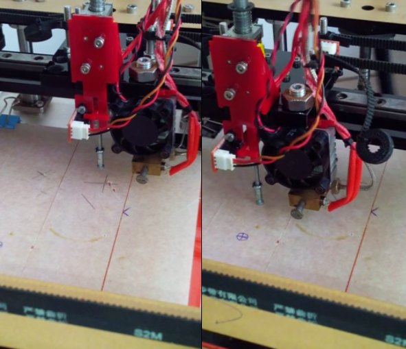
He’s since switched over to use a solenoid actuator with an optoisolator to determine the position. The actuator extends an M3 screw which will touch the bed — as the position is adjusted, it is possible to adjust the bed using software for a perfectly level bed, every time.
Relatively speaking, the hardware aspect of this was quite easy to do. [Rupin] is now cleaning up the code and when he’s happy with it he will publish it as part of the Marlin branch of printer firmware.
Alternatively if you’re looking for more of a challenge you can try using temperature force sensitive resistors to level your bed…


Disclaimer: I work for DeltaMaker
That said, this is how we’ve been doing our touch probes for over a year now – https://plus.google.com/104012815742569035024/posts/es6J8EEocmq
I never came across your design while I was looking around for options to make this part of my printer more robust.
Doesn’t the limited stroke length of the solenoid coupled with the movement of a switch create some rather difficult choices in terms of commercially available parts, no?
Not really. The solenoids we buy in batches of 200 from SparkFun, and the switches are pretty standard. Only thing non-standard is our mounting brackets.
I’ve never liked the servo method of lowering the probe, but any extra hardware on the hot end is unwelcome IMO.
With a metal bed I like the hall effect sensor method.
I also dislike constantly driving the Z axis to adjust for tramming, but not sure of a good way without adding loads of motors and weight to the platform.
Any extra weight on the moving print head is unwelcome, for sure.
We got to make appliances, and not machines.
We have to accept the fact that the bed is going to be removed over and over, and trimming or leveling the bed is the most boring activity on a printer, but it is one of the most important one to ensure a good print. That coupled with low access to precise machining, plate bending, quality( bowed, bent) plates in India, I think its an wise decision to let the software do the dirty work.
What you also get with constantly driving the Z motors is the inability for them to “time out” and reset to a full-length step, causing inconsistencies and requiring you to choose layer heights that are divisible by your full step length. Auto bed leveling actually will _improve_ the quality of your prints not only by making sure that microstepping is on at all times, but also there are points where the added noise can end up looking better.
That sounds like constantly driving the Z is covering up other issues rather than addressing them. But the microstepping is an interesting point. Is this timeout in the firmware or stepper driver?
Firmware. By default, repetier and marlin both will deactivate the Z driver in order to have less stress on the driver which will cause the stepper motor to cog to the nearest full stop position.
I understand that mechanical switches have repeatability issues, and hal sensors need a metal bed. How would ametal probe with a hal sensor on the probe be for accuracy / repeatability?
1) Magnets tend to lose magnetism over time, if not placed between two ferromagnetic plates. Long term repeatability is definitely questionable. Maybe its not that big a deal, because the only problem is one failed print, and 30 minutes for recallibration.
2) Metallic plates tend to be bowed/bent, atleast that’s the kind we get in my city. No one has information on how much this bowing or bending is, and varies between plates.
3) I have always thought of this problem this way- The build plate and the method to sense should be independent of each other. An inductive probe will only work with metal, not with glass, which is a far more cheaper, and absolutely flat (atleast in the scales we work with) material to work with.
HAL sensors are very temperature sensitive.
Microswitches have a high repeatability actually. Around 2 micron as far as I measured.
You can put a thin piece of some ferrous metal between the glass and the bed heater, would also help to spread the heat more evenly.
Not sure how thin you could go, can you get steel foil?
‘steel foil’ = shim stock.
“I understand that mechanical switches have repeatability issues”
Not according to Thomas Sanladerer.
VVS claims yet another victim. sigh.
This time, it’s actually framed about OK though, just not tracking well a bit at the start.
That solenoid looks a bit heavy. A micro servo can’t be a quarter the weight of that thing.
Thanks for pointing this out.
Use an optical sensor, like a bright LED shining out through a slit and a phototransistor looking at it through a pinhole. The light and the pinhole are angled to look down in a V so the sensor sees the image of the narrow beam of light on the surface only when the surface is at a certain distance. The pinhole is projecting the image like a camera, so you can build in baffles that let light to the sensor only at a very narrow angle.
Then you simply move the sensor up and down until it finds a bright light, and measure the exact position where it is the brightest.
Better yet, pulse light at some known frequency and filter other frequencies out at the sensor, so it isn’t fooled by ambient light.
A lot of people use glass or mirrors as the bed, so light doesn’t really work there. Otherwise you could just use those IR distance sensors.
Ultrasound can be accurate enough, but not accurate and cheap.
That’s not really a concern. You could use a UV light, because glass isn’t transparent to it.
That solenoid looks huge and heavy compared to a micro servo. I have a servo activated activated endstop, and in the down position is just presses lightly against a stop block. That solves the calibration issue, I get contact position repeatability within 0.01mm.
The setup with all the acrylic mount + probe+ solenoid weighs about 50gms.
Yeah…and the micro servo I use weighs about 7 grams, wire included. No more than 3-4 more grams for the microswitch and the probe arm.
That is amazing. I had a lot of torque available on my NEMA 17 motors that this solution doesn’t seem to be a bottleneck, yet.
The servo method has never worked for me. Firstly, in 2 weeks, the servo started to become noisy. Maybe the potentiometer that provides feedback got damaged. I had to upgraded to a better quality servo, which did not have plastic gears and weighed just as much as my current solution.
If you were to check my youtube videos, I also tried another probing method, but it was semi automatic, and required manual intervention.
Don’t need a bulky solenoid at all. What if you put a magnet on the top of the probe so when it was pushed down it would stick to the top of its shaft. Then you’d need some way to release it and let it drop to its lowest position. Rest of the mechanism is the same, pretty much. Gravity and Z-axis motors do all the work.
Is there a reason to use anything other than a glass bed?
Then you don’t have the joy of hacking up cumbersome & complicated leveling devices, or pontificate on ones even more so.
Float glass is dead flat, and will stay that way. 3mm (window glass) will be fine, as will 2mm from picture frames or 6mm for larger beds.
Measure the corners, level, done.
Etch (acid or sandblast) the surface to make the plastic stick better. Some people find it doesn’t stick to the glass and use tape. You’re probably using tape anyway, but at least your bed is flat.
I’m toying with the following method for automatic bed levelling, and would appreciate some feedback:
1. Use a Z-limit switch mounted on the hotend mounting bracket itself. The Hotend is mounted on a hinge, such that if it touches the print surface, it lifts and triggers the switch. This is fairly simple and straight forward.
2. The bed itself is supported in 3 positions, in two adjacent corners, and midway of the opposite side. This makes a nice triangle, which is easy to level by adjusting only two set screws – the mount in the center of the opposite side is fixed. The set screws could simply have a thumbwheel or butterfly nut, etc for manual operation.
The next part gets a little tricky, as it is where the automation comes in.
Rather than manually operating the thumbwheel to adjust the two set screws, use micro steppers with a worm gear mounted on the platform, interfacing with the thumbscrews (changed to gears, effectively). (For reference, I am constructing an OrdBot Hadron). The Micro Steppers can be purchased from DX.com, for a couple of dollars, and they weigh about 10g each, I believe.
The main controller would then move the head to a position above the fixed print surface support, lower it until the limit switch on the print head operates, then move to a position above each of the two opposite corners, and repeat:
1. Lower the head to the previously determined Z-home. If the limit switch operates before the supposed Z-origin, use the micro steppers to lower that corner of the print surface. As the Z-limit switch releases, lower the print head until it operates at the Z-origin. Basically, let the microstepper do the work of operating the thumbwheel on a repeatable basis.
So, the question comes in:
How would one control the two microsteppers using a standard RAMPS board? (I actually have an Azteeg X3). In theory, each of the microsteppers could “share” the Z-axis driver, with a relay of some sort to control which motor is actually active, although I can see problems with that, not least the fact that the microsteppers will certainly not sink 1.2A!
I guess an alternate approach would be to use something like the ULN2003 drivers to drive the microsteppers, controlled by a spare GPIO from the RAMPS board.
Has anyone done anything like this before?
Almost exactly 4 years ago: http://pleasantsoftware.com/developer/3d/2010/09/26/keep-it-simple/
Vibration motor on the print head. Microphone on the bed. Lower the head until the mic picks up that the head is touching the bed. Next use software to compensate.
Simple, cheap and uses the actual print head as the Z sensor.
is this geeetech 3d touch the same with the bl touch http://www.geeetech.com/3dtouch-auto-leveling-sensor-for-3d-printer-p-1010.html