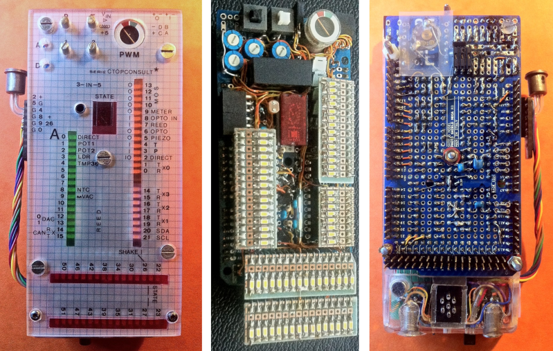
What doesn’t this Arduino Mega shield have? Ponder that as you realize that it doesn’t just attach itself to the pin headers, but uses every single one of the mega’s connections.
This isn’t a bunch of components kludged together either. [Carsten] is an a EE and that explains a lot of the really great choices he made like buffering, opto-isolation, and the clean assembly despite a schematic that’s so busy it’s difficult figure out where to start.
So, what does it do? Looks like a one-stop-shop for quick prototyping needs. For instance, there’s a pushbutton, toggle-switch, and a couple of trimpots for quick and easy input. At the center of the board is a 7-segment display, and multiple rows of LED bar displays (assembled from SMD components and protoboard) to provide feedback to the user.
There are also a number of sensors at the party, including a mercury shake sensor, temperature sensor, microphone, thermistor, and light dependent resistor. If what you need isn’t on the board there are multiple options for connecting external gear including opto-isolated input and output, and a LEMO for digital I/O with another for analog. All of that and we forgot to mention the moving coil voltmeter that measures PWM.


Or a few wires for a $7 SPI based color LCD…
;)
There needs to be some sockets to allow you to plug in other things as the Mega doesn’t have pins on the bottom. If everything you’re after is provided by this board then it is great but if you want anything else then you’re going to have to solder it onto the bottom.
This is a tester, not a regular arduino shield, as such it would be the top shield in the stack. This is a great tool for dwbugging designs. It also could never be replaced by an “SPI based LCD” because it would not show the real pin status, or it would just take the place of the LEDs and require a microcontroller just to interpret it, and it would be less useful that way. This is not some board you put in your project and forget about, it’s a tool. It’s kinda like these for Arduino Mega: http://www.pcengines.ch/test.htm
I can’t spell debugging, lol
Did you really have to explain this?
Did you really have to reply with no constructive information?
Yes.
Plus, most SPI based LCD shields are wired for UNO pinouts, which do not also work with MEGA pinouts.
At least not if you want to use hardware SPI anyway.
Would be pretty sweet if they were to do a limited run of boards, in a DIY solder yourself version. Maybe partner with another reseller?
Thanks for the explanation. I’m not very good with this stuff, trying to learn through osmosis really, so you helped me understand what this is for and how it is useful.
Huh, I guess it will be what, 2-3 weeks before sparkfun/adafruit/someRandomChineseWebsite have this? Not to speak bad of them, I want one of these and I’m too lazy to build it myself.
What a good little tool though.
For the standard Arduino there is already my Blinkenlight Shield: http://blog.blinkenlight.net/experiments/hardware/. The schematic and layout are open source. If you are in Germany you can even order it as a product, e.g. jere http://www.amazon.de/gp/product/3645651462/?ie=UTF8&camp=1638&creative=6742&linkCode=ur2&site-redirect=de&tag=wwwblinkenlig-21
The initial idea for this shield was to have a light show as well as a simple debug tool.
Is it really a 7-segment display? It looks to me like an HP-Hex display (power hungry mutha with 4 bit input).
Using the meter off of an old cassette player…. priceless!