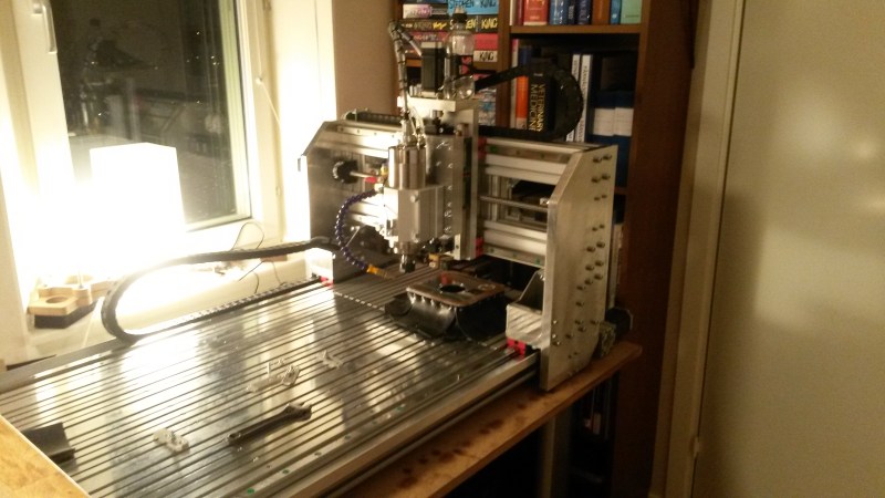
[Jens] aka [Tumblebeer] has compiled an impressive overview of the Tumblemill, his homemade CNC mill. It warms our hearts to learn that [Tumblebeer] was inspired to pursue electronics by projects featured here on Hackaday, even if it means he dropped out of med school to pursue electrical engineering. We’re glad he’s following his passion, though, and reading through his blog reveals just how far he’s come: from fiery disaster in his first projects to a gradual obsession with making a CNC device, [Tumblebeer] has made plenty of mistakes along the way, but that’s how it should be.
His first iteration was a CNC router that used rubber wheels as linear bearings. It worked…barely. His latest build grew out of meticulous Solidworks modelling, with a moving gantry design constructed largely from aluminum, and upgraded linear motion: this time a bit overkill, using HIWIN HGH20CA blocks. Rather than sourcing a traditional spindle mount, [Tumblebeer] opted for the housing from a LM50UU bearing, which provided both the perfect fit and a sturdier housing for his 2.2kw spindle.
Visit his project blog for the details behind the mill’s construction, including a lengthy installment of upgrades, and hang around for a demo video below, along with the obligatory (and always appreciated) inclusion of the Jolly Wrencher via defacing an Arduino.


That is a nice CNC Mill. And I think HGH20CA blocks are not an overkill. They are decent and a ticket for serious precision.
Actually, on my current build i use HIWIN HGW25 on my Y axis, and THK HSR30 on my X axis… the Z axis will probably use HIWIN HGW20 and i do not think that is overkill at all… That is for a 1000x800x200mm machine built in aluminium extrusion.
When you read through the specifications listed by the manufacturer, these bearings really are a massive overkill. I haven’t got the exact number in my head, but it’s rated for a load of several tons.
That said, the alternative is supported round rails, which would be an equally massive “underkill”. The profile rails really are great and you’re never wrong going for them. When building you always have to decide what parts are worth spending more money on and what is less important (though balance is of course most important, always), and the linear units really are possibly the most important part of the machine.
I, for one, like the inclusion of not one, but many, Arduinos.
Not part of the Arduino-bashing crowd (largely cos IDGAF), but I have to agree!
Throwing money at the screen. Nothing is happening =(!
Nice build , Epic commentary.
It’s nice to know that when you have the blues, you can take a look at your enourmous penis and it melts the blues away.
Davinci, didn’t I read that in your notebook?
I think that’s inappropriate. This is why we can’t have nice things.
Excellent commentary with a bit of fun.
Really nice build.
The music was the icing on the cake.
Mom! I want one of these for christmas :'(
Not sure mom can help you anymore with the enormous penis..
If you start building now, you might be done by christmas!
Not for nothing, but I do the same with my arduino. I push firmware updates over wifi to the delta 3d printer I built. It has worked out fine for me. I am using one of those cheapo tplink routers. It was as easy as ddwrt, to complete the job I used a cheapo pharmacy cigarete lighter to usb charger to power the router, which in turn is powerd by the 3d printer psu. Has held up for months now. USB over ip for the win…..
I used this guide as a tutorial….
http://www.madox.net/blog/2013/01/04/tl-wr703n-example-project-3-wireless-3d-printing-or-2d-printing-or-just-simply-wireless-usb/
This mill is positively dripping with Arduinos! Well done sir!
Great mill, would love to have a tool that capable.
What an odd tool path on the companion cube though (first video 2:00). What is the reason for the ‘back and forth’ type motion across the surface of the piece versus traditional pocketing where you plunge, then move through the cutout shape in a spiral motion?
That tool is actually a ballnose end mill, 0.8mm in diameter. I’m doing what’s called 3d profile milling, where you move back and forth removing small amounts of material with a very small stepover (here 0.08mm) to reduce scalloping. This makes more “natural” or “flowing” shapes possible than what a traditional end mill might achieve.
Of course you could use a normal path for this as well, but that’s a very advanced feature (like “constant scallop” and other forms of black magic) that my cam software is not able to do. The usual way of 3d profile milling is this parallell version, or a waterline toolpath. I prefer the uniform finish from the parallell milling, though I admit I haven’t been playing around with it much yet.
My friend,
Why did you move the placement of the ball screws from above the linear rail to slightly below and to the side? I am referring to the Y axis.
Stability mainly. If I’d wanted to place the ballscrews above the rail, I I would have had to leave that entire length of plate open to flex all it wanted. Granted, it would only be about 10cm of 2cm alu plate that could flex, but when a hundredth of a millimeter matters…
Also, this way I could protect the ballscrews from swarf, something I wish I could do for the rails as well.
Thank you,
I am planning to build a concrete (not resin, but water mix) mill for the fun of it.
Ypu seem extremely knowledgable from your blog. Where did you learn the particulars of CNC mill design? I usually creep the cnczone forums.
For the linear rails, why do rubber bellows not work?
I’m sorry, but he dropped out of medical school for engineering? It isn’t like he dropped out to become a greeter at Walmart. Last time I checked he could still be called Dr. as long as he has his PhD. In fact, a good PhD engineer with a PE is a lot more accurate than a “doctor”. Remember, the call it medical practice for a reason. SMDH.