[Daniel] received a grant from the University of Minnesota’s ECE Envision Fund and was thus responsible for creating something. He built a runner’s GPS logger, complete with a screen that will show a runner the current distance travelled, the time taken to travel that distance, and nothing else. No start/stop, no pause, nothing. Think of it as a stripped-down GPS logger, a perfect example of a minimum viable product, and a great introduction to getting maps onto a screen with an ARM micro.
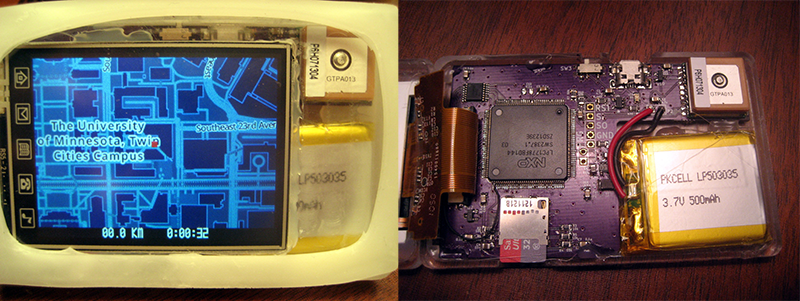
The build consists of an LPC1178 ARM Cortex M3 microcontroller, a display, GPS unit, and a battery with not much else stuffed into the CNC milled case. The maps come from OpenStreetMap and are stored on a microSD card. Most of the files are available on GitHub, and the files for the case design will be uploaded shortly.
The CNC machine [Daniel] used to create the enclosure is a work of art unto itself. We featured it last year, and it’s good enough to do PCBs with 10 mil traces. Excellent work, although with that ability, we’re wondering why the PCB for the Runner’s GPS is OSH Park purple.


>Excellent work, although with that ability, we’re wondering why the PCB for the Runner’s GPS is OSH Park purple.
I’m not sure this is universally the case, but the homemade boards I’ve built, and I’ve made probably a hundred, tend to do poorly with long-term vibration. The pads pull loose from the board because they lack through-hole vias. I get better life with my milled pcb boards soldered on both sides, but a set of brake lights I made for a friend’s Pinzgauer lasted less than 5000 miles before the traces began to crack. Dipping the board in epoxy post-build helps a bunch, but at that point, a fab house seems awfully attractive.
It looks like the CNC is not quite up to PCB milling spec.
“The CNC mill is taking far longer to get precise enough for machining the traces I need”
https://sites.google.com/a/umn.edu/tayl0518-runners-gps/updates/pcbupdate
At that time, yes. Since then, it has improved to where it can definitely do PCBs:
https://fc65b08ce27786f4d35a7e557ff4b44c794b4f93.googledrive.com/host/0B_Cyg0CezJwDUDdtbC1nc2liMm8/20140330_00.jpg
That board has its imperfections (note trace width variation, especially at the upper right) but the machine has only improved since then.
For vibrations, SMT parts are doing a lot better than through hole counterparts mainly because they are much lighter. As SMT parts they are designed to be soldered down on one side. :) Having a solder mask also help the adhesion of the traces/pads.
For heavy parts, you want to glue down parts or tie them down with strings/cable ties onto the PCB. Choose radial packages for their lower center of gravity and they also easier to tie down.
>Excellent work, although with that ability, we’re wondering why the PCB for the Runner’s GPS is OSH Park purple.
If you have ever done fine pitched (0.5mm) SMT assembly, you’ll find that a properly fab PCB with solder mask is hell lot easier to solder than a home made one. Being able to do finer spacing than 10/10 with vias also do wonders for routing a design.
With money from someone else for the project, why would you try to make life more difficult for yourself?
And it’s still a pain in the ass to do reliable homemade plated through holes.
I second this, when I need via’s I usually just order at OSH park because its cheap as hell.
That’s a huge part of it. I decided it wasn’t worth the misery of tracking down why something didn’t work, only to discover a bad via. Or a tiny fleck of copper in the isolation paths.
Milling a board this complex also takes forever, and if you mess anything up (especially aligning the front and back), you ‘get’ to start over. Time is valuable.
I’m all for milling simpler boards, though. When they’re [mostly] one-sided and take 10 minutes to mill, the convenience is hard to beat, and it’s much easier to re-spin a board once you realize the mistakes you invariably made. I’m just lucky my mistakes on this board were easily-correctable.
Nice project, congrats [Daniel]!
I wonder for how long can you run on that 500mA battery, because of the display and GPS power consumption. Two hours maybe?
The display backlight would be the limiting factor there, my Navspark based logger draws less than 50 mA during normal GPS operation.
I’ve only run down the battery once, and it took 4 hours. Mind you, that was with a bunch of re-flashing in the process, and the LCD on for most of the time, plus a bunch of GPS fix time (taking more power than tracking).
I would expect to be able to get it up to around 6 hours. The GPS only draws ~20 mA when tracking, and the LCD can be off most of the time, but doesn’t actually draw all that much to begin with (maybe 20 mA for the panel and the backlight; I use it at night, so it’s dim).
The real task is some power management. Supposedly the micro can get down to ~14 mA in sleep mode, though I haven’t gotten there yet. Similarly, the screen refresh is horrible- not only does it take maybe 0.4 seconds (during which the micro is running full-tilt), but it’s reading from the SD card that whole time, which I assume adds significantly to the draw. There’s not enough RAM to cache the whole screen, but some creative code should be able to reduce the SD card-reading significantly.
In practice it probably doesn’t matter, since I don’t run for anywhere near that long, but I’m lazy and don’t like charging things, which is great motivation.
This is why software like espruino is so attractive, they have already done all the hard work to lower the idle power consumption.
If you want to do it on your own, then you have to make sure all your code is non-blocking so that it always comes back to your main idle loop where you put it into low-power mode.
I think that’s actually an LPC1778 (LPC1778FBD144). I’ve used the LPC1788 (another cortex M3) and can attest that these micros have about every feature you could want. 10/100 Ethernet MAC, SD card interface, LCD driver, USB, gobs of UART and SPI, RTC, ADC/DAC, and an external RAM / Flash interface with DMA. The 1788 even comes in a 208 pin QFP to break out all the features it has. There is another version which also comes in 208 pin but is a cortex M4 with a cortex M0 on the same die, which is handy as it gives you an FPU. The only thing I can even think to say it doesn’t have are SATA and a GPU. But this micro is pretty slow to expect either of those, I think the M4 tops out at around 200MHz, so that’s expected.
If you’re looking for a very featureful embedded linux controller, this is it. It’s a lot slower than say, a raspi, because the clock speed is a lot lower. But it’s very powerful and very I/O rich.