The T-962A is a very popular reflow oven available through the usual kinda-shady retail channels. It’s pretty cheap, and therefore popular, and the construction actually isn’t abysmal. The controller for this oven is downright terrible, and [wj] has been working on a replacement firmware for the horribly broken one provided with this oven. It’s open source, and the only thing you need to update your oven is a TTL/UART interface.
[WJ] bought his T-962A even after seeing some of the negative reviews that suggested replacing the existing controller and display. This is not in true hacker fashion – there’s already a microcontroller and display on the board.
The new firmware uses the existing hardware and adds a very necessary modification: stock, the oven makes the assumption that the cold-junction of the thermocouples is at 20°C. The controller sits on top of an oven with two TRIACs nearby, so this isn’t the case, making the temperature calibration of the oven slightly terrible.
After poking around the board, [WJ] found an LPC2000-series microcontroller and a spare GPIO pin for a 1-wire temperature sensor. The temperature sensor is placed right next to the terminal block for the thermocouples for proper temperature sensing.
All the details of updating the firmware appear on a wiki, and the only thing required to update the firmware is a serial/USB/UART converter. A much better solution than ripping out the controller and replacing it with a custom one.


VERY nicely done. I’ve seen replacement controllers marketed, and it always seemed like a shame nobody had figured out how to reprogram the built in controller. Bravo!
I own this oven and yes the stock firmware is almost unusable and the profiles are off. Modifying and releasing the firmware is amazing. Thank you in advance.
Technically it’s not a modification of the existing firmware – it’s a re-implementation. Not sure I would like to touch the original firmware with any length of pole. :) It needs more work in the UI part to be able to select/modify profile without recompiling, but it’s a start proving that it can be done.
Same here and agreed, this will definitely be on my todo list!
Freaking. Yes. I took it apart, looked up the datasheets, identified some of the pins of interest, but just have not had time to attempt this. Now I have a new reason for Thanksgiving!
Absolutely awesome and a great example of exactly what I come to HaD for. If I hadn’t just gone the toaster oven route I’d now be looking at T-962s on eBay in a very different light.
I’ll have to keep this in mind for next time I need to use my oven. There are a lot of changes I want to make to the unit, and now that somebody’s done the base work of tracking down all the pins there’s a lot of enhancements that could be made:
First off would be to get deep enough into it to reverse the flow of the cooling fan. It’s absolutely stupid that the cooling fan pushes air through the unit and out the bottom, because that also pushes the fumes out the same way. I should be able to hook a dryer duct to the back of the unit and exhaust everything outside, but not without reversing the fan.
The next thing would be to utilize the firmware framework to add PWM to the cooling fan so that it can sustain a low airflow through the oven cavity. Without that kind of airflow, the heat applied to boards is *extremely* uneven. I’ve resorted to putting a separate fan behind the unit to and carefully adjusting the distance to get enough airflow moving without screwing up the ability of the system to heat up. Being able to PWM the built-in fan would make that radically easier.
Finally, I’d want to permanently install an ft232 (or BT?) on that UART so I can just load up a serial terminal to drive the thing. I’m assuming this new firmware solves the stupidity with the button-polling in the native firmware, but it’s still too restrictive an interface for me, not to mention lack of logging…
You want to push cooler outside air into the unit as you fan won’t need to handle the hot air and the condensation of the flux and other stuff in that fume. Alternatively but more complicated way you can suck the air out through filter(s) + some way of chilling the air before reaching the fan.
True. Unfortunately that leaves some kind of external enclosure the only means of capturing fumes, because the entire bottom of the unit is open.
Though if the fan is on at maybe 5-10% (enough to even out the heat profile) I’m not sure if there’d be enough heating of the fan to matter, or whether enough material would make it through to the fan if I were to put a basic filter before it.
PWM has already been implemented for both heater and fan, and the fan runs slowly during the entire cycle. It does indeed help a lot with heat distribution.
Reversing the fan is an interesting mod, not sure how well it will stand up to repeated cycles of hot/cool air though, but the ducting idea is an interesting one!
I have a debug cable coming out of the left-side vent so that I have the entire ISP connector available for easy reprogramming, BT sounds like a nice mod – just make sure you can control reset and isp pins to be able to enter ISP mode automatically.
The buttons are still polled as I haven’t had time to figure out how interrupts work on the LPC2k-series, but they’re polled way faster than the original firmware.
Great work. Also Brian, respect – you’ve been churning out a ton of quality articles recently: )
Good article and good project, I have a T-692 and its like hearing an loud smelly opinion of soldering that you don’t quite believe in and I end up babysitting it during a run Between runs the T-692 kind of just lurks, a possibility not fully developed.
Dave Jones of EEVBlog fame always says “Don’t turn it on, take it apart”, and that was indeed the first thing I did before turning this one on as I had a suspicion that it would full of masking tape – and of course it was! Having read http://www.instructables.com/id/T962A-SMD-Reflow-Oven-FixHack/ it was obvious something had to be done.
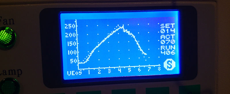
Here’s a trick for you if you think it’s too loud: When you have cold-junction compensation installed you don’t really need that noisy small fan running as the board actually isn’t getting hot. It reaches 45C after repeated cycling of the lead-free profile but that’s about it. Everything is pretty much quiet until the last 30 seconds or so when it really has to work hard (and fail) to maintain my cooling curve as can be seen in the graph. The annoying part about the TC interface they did is that it won’t measure negative delta, so you will always read _at_least_ the controller board temperature. Replacing the TC interface with a more robust one will definitely make it possible to ditch the small fan completely. As I see it the small fan must have been an afterthought trying to compensate for the lack of cold-junction compensation.
I almost bought one until I read about the firmware. Building my own, probably work out costing a little bit more, but it will be exactly what I want.
Fantastic! Will you continue to develop this project? Maybe I’ll decide to purchase this oven.
Here are my two cents.
A better solution would be using MAX31855K. It uses SPI (read mode only) for reading digitized temperatures at both hot and cold ends of thermocouple.
A conversion time is 100ms max. Additionally it detects faults (shorted or opened ends). It’s cheap and easy to use (SO8 case).
This is possible in case that at least 3 GPIO (easy software protocol) or SPI pins are available.
This will continue to be developed. I will have to bring some of my menu system code in from another project and architecture (the main LCD code also originates from an 8-bit AVR system which is why it may look a bit off on a 32-bit system from an optimization perspective). This initial design was a bare minimum modification which regulates fairly OK, but I got a bit inspired by the ESTechnical ideas (and they featured the MAX31855K) and I thought it would be nice to allow measurements on the actual boards as well so I made this board that I’m going to do some tests with:
https://oshpark.com/shared_projects/exlUasRm
It’s not the MAX31855K I’m using but the MAX31850K (4 of them). I figured I can use two channels for the existing thermocouples and two that can be attached to boards and then see how much the temperatures differ (selecting which combination of sensors that will be used for feedback might be handy). The MAX31850K utilizes a 1-wire interface as well which makes it a lot easier to interface to the existing board.
You will need four pins or three pins + some logic if you want to run two 855’s as they need their own separate chip select. It IS possible to get to four pins on the board if you don’t use the analog inputs but it’s a lot more work to do than utilizing the 850’s instead.
Note that one solution doesn’t have to rule out the other, I’m planning to support a completely unmodified board (where you have to tell it the board temperature manually), the simple cold-junction compensation and then the more exact direct conversion of the 850’s. If anyone hooks up some 855’s let’s just add that too. Auto-probing for the 1-wire devices is simple, not sure if there’s a fool-proof way to determine if you have those read-only SPI devices hooked up somewhere. It would be nice to be able to auto-configure as much as possible.
Looks great !
However I am curious how this would compare with a home brew controller with a modified IR oven. A buddy of mine and I re-tasked a convection oven last year with an MSP430 launchpad ( MSP430G2553 ) + custom expansion board. using pseudo PWM to control the AC in. While it worked, and had an LCD display to output important information. It had no where near as much control as this. Especially considering I only implemented a 4 stage profile . . . this looks to be 48 separate stages ? Very nice.
To be sure – You can get away with paying less using a convection oven + custom controller. At least initially. In the end though this modification could save one a lot of time and frustration. Passed that, convection ovens are typically very poorly insulated. SO one ends up spending even more time + money insulating the thing properly in order to reach, and maintain a certain heating profile. Passed ~225C it becomes very unwieldy attempting to control heat in an uninsulated convection oven . . .
Now, as for wireless communication goes . . . I foresee yet another use for the ESP8266 ;)
The 48 separate stages is a function of me trying to be somewhat compatible with how the EEPROM layout was done in the original firmware. Each “stage” is 10 seconds long (15 in the original firmware) and the temperature between them is linearly interpolated so for the first 10 seconds it ramps between the first and the second value and so on. That gives you a maximum run-time of 470 seconds (which is why the graph stops at 8 minutes). It makes it very easy to input any curve, but it might be way overkill in practice. I had no problems getting my profiles to look like the ones Amtech suggests for the solder pastes I use with the current setup though. Looking into how to add a “bake” mode, as that should be very simple because of the constant temperature. The time is substantially longer but no real “profile” is needed so the fixed maximum time of the reflow profile probably won’t be a problem. I’ve never seen a reflow cycle running for 8 minutes (not counting the initial run with the original firmware of this oven). :)
But yeah, maintaining 245C in this oven is tricky when you have the fan set too high.Luckily you don’t really have to maintain it for very long even for lead free. I can imagine that an oven with even less insulation will be a major nightmare.
ok I didn’t read the datasheet for the DS18B20 but this statement really confuses me…
“soldering both Vcc and ground pins to the ground plane”
ok datasheet saves the day (RTFM)…
“DQ) Data Input/Output. Open – drain 1-Wire interface pin. Also provides power to the device when used in parasite power mode (see the Powering the DS18B20 section.) “
Yep, not a typo.. It certainly looks all wrong to pull Vcc low though! :) It was way simpler to just hook the 1-wire sensor up with parasite power (note that it needs strong pull-up during conversion, so no other communication can happen during that time. My expanded thermocouple interface will have to be powered as there are multiple sensors on the bus doing conversions simultaneously.
Pin Description on page 2 datasheet.
>Optional VDD. VDD must be grounded for operation in parasite power mode.
Actually there is no confusion.
First sentence: You can also run the part with Vcc for power and not rely on the DQ to supply “parasitic power”
Second sentence: or only use Ground and DQ which provides power.
From a thermal and easy of use point of view, just connect the *optional* Vcc pin to ground. The extra pin would help a tiny bit on thermal conduction of the ground connection. I would have used a surface mount part and glue it to the underside of the pads to the terminal block to get much better thermal contact.
Main reason why I placed it where it ended up: Because the trimmers block the airflow from the small fan it would not be directly in the airflow. It definitely is accurate enough for this purpose – the opamp construct dealing with the thermocouple input generates more error, but it’s reasonably close. I’m going to verify it against the 4-channel thermocouple interface I put together (mentioned above), that one uses DFN parts very close to the terminal block to get proper thermal conductivity.
Great mod! Maybe I’m little tired and wrong: where is firmware to put in with UART?
A compiled and ready-to-go hex-file has not been published yet as at least some method of selecting and modifying the profiles will have to be implemented, as it is right now the reflow code has to have the profile compiled in. This will change shortly, but as I will be on a business trip to Tokyo next week it will have to wait a few days until I get back.
So I managed to implement at least a basic profile selection tonight (see wiki for updated screenshots), but still no way to customize the eeprom-based (custom) profiles. The firmware definitely rapidly approaches the point when it might actually be usable by other people than myself so a prebuilt hex-file might be in order if there’s any interest. Currently the firmware knows about three Amtech solder paste profiles: The low-temp LF NC-31, the 4300 leaded and the SynTECH-LF standard lead-free.
I just put prebuilt firmware on the wiki: https://github.com/UnifiedEngineering/T-962-improvements/wiki/Prebuilt-firmware
I managed to get a super simple UI to edit the EEPROM profiles running as well.
Great work, I am following this closely, as I just received the small oven, T-962 built January 2015, very fresh. Yes, the earth connection is made on painted face. Replaced the masking tape, Installed the cold junction compensation DS18B20 and started flashing. I tried USB to serial dongle on Win7. I manage to get the blank screen with n_ISP tied to gnd. Does not respond to F1 down on power up. In the LCP2000 utility I cannot select the LCP2134 and cannot communicate. With FlashMagic no luck either. I suspected my USB serial dongle, so I dusted off an old laptop with WinXP and serial port, made serial cable and tried that, still no luck. Any suggestions there please?
On the other side, I am planning to add a little DC fan with stainless propeller, mounted on stainless tube to minimise the heat transfer to the motor shaft. It will be sitting at the top of the oven, on sub-plate, fan in-between the two lamps with a shroud to direct the circulation. I want to make it in to IR/convection oven as the big boys do, as drawing fresh air in with the large fan does not appeal to me. What do you think?
Panic is over, I managed to flash V0.4.1 with FlashMagic. My board has got 5 ISP pins. Used FDI USB-Dongle interface. All good. Going to set it up now. Thanks for sharing the new hex life of the oven!!!
That sounds great!! Yeah the board only have 5 pins, the confusing part was that I added a 6-pin connector with the added 3V3 rail to make sure that the serial interface was only powered when the oven was on. It’s described in the text but not entirely obvious from the picture
Thanks for posting this. I was hoping someone would improve the firmware without ripping out the entire controller board.
I noticed your oven has a LPC2134. Mine has a LPC2144 and others have reported a LPC2148. Do you know if your code will run on the other processors? Have you heard of any other circuit changes that would affect the compatibility of the firmware?
I would like to ask a similar question.
What type of oven you have T962A or T962? Do you think that your mod will work on both?
Is it possible to readout original FW or it’s locked ?
Oh interesting! I was not aware of the multiple different MCU variants used. I took a brief look at the LPC214x datasheet and it looks very similar (identical to the LPC2134/01 I have in mine except for the addition of USB on pin 10 and 11). The important thing is that it supports fast GPIO (the difference between the regular 2134 and 2134/01).
I’m using the small T-962, but the T-962A works in the same way. The heaters are driven in a different way using a solid-state relay, but the control pin is the same. I would be very surprised if this did not work straight out of the box on the other similar models. It wouldn’t make sense for them to have separate firmware.
My CRP word was not programmed so I could make a copy of the flash image before messing with it, so if someone with a T-962A attempts this I will be very interested in hearing the results! The same goes for the different MCUs, it would be good to list all the combinations found in the wild.
As long as the capacity of the flash and RAM will be sufficient it should be OK. Maybe the variant build will be required.
Looks like it should work without any variant changes. I’m assuming 16kB RAM and the code is way smaller than 64kB still so it should be OK on all but the smallest parts (the ones with 8kB of RAM/32kB of flash).
I just tried connecting to the controller using the lcp2000 flash utility with no luck.
I used the DTS/RST option and also manually setting n_spi to ground while resting.
Wjxnk could you please provide detail or input .
Thanks .
That’s a bummer! Let’s see: Try without DTR/RTS, provide the utility with XTAL frequency 11059 (kHz), baud rate 57600 (the highest that xtal frequency will handle in bootloader mode). If you hold ISP pin low and then bring reset pin low and then release it again while still holding ISP low you should then be able to hit Read Device ID and have it return “LPC21xx” in the Device box depending on what MCU you have. If it still isn’t connecting can you verify that you have TX and RX correctly hooked up (and GND of course)?. What UART interface are you using?
Still no luck . I tried on a ft232 and a mcp2200.
Not sure what’s going on.
Just to confirm, when I hold ISP low and toggle reset red led turns off and both green LEDs on front panel turn on. Does that sound right ?
That is indication that you entered ISP mode (or just having the MCU in reset mode). The output pins for heater and fan are floating so the buffers tend to turn on both loads. As those pins are active low you will need weak pull-ups to 3v3 to get rid of that behavior.
And it is this utility you use? : http://www.lpctools.com/downloads/LPC2000%20Flash%20ISP%20Utility%20v2.2.3.zip
Yes,that’s the software I’m using . in will try on a different computer later today.
I added a screenshot of my LPC Flash Utility to the Wiki showing all the settings. I also verified that you can keep ISP pin low and communicate with the bootrom after you let go of the reset, that might make it slightly easier to repeatedly enter ISP mode initially (but of course you have to float ISP pin to get any real software running). First things first, you need to get the MCU to identify itself. Can you verify that you have ~3.3V on both TX out from the MCu and RX going in when your LVTTL serial interface is hooked up?
followed the wiki step by step , and still no luck. What UART interface are you using ?
Hey bmesuh, I had your same problem, and after few tries I discovered that looks like to boot sequence is slightly different.
So, the ISP standard mode is:
ISP Pin LOW + RES Pin LOW -> RES release -> ISP release
After this the T-962 with LPC2144 goes in a sort of boot display mode (a logo with a webpage on the LCD), after that you have to do the opposite:
RES LOW + ISP LOW -> ISP release -> RES release
and it turns on the lamp on.
Then, just set 9600 baudrate and connect.
…aaand sry for the grammar “orrors”
I was able to connect to the NXP processor using the LPC flash utility. My board is a little different than the one in your photo so I did a little reverse-engineering of the ISP connector. The following assumes pin 1 of the ISP connector is closest to the red LED. My ISP connector has 5 pins.
Pin Function Serial adapter
1 P0.14 RTS
2 Reset DTR
3 TXD0 RX
4 RXD0 TX
5 Ground Ground
I connected to it via a FTDI UM232H-B adapter. It read the part number properly and downloaded the code from the flash (it appears to be unprotected).
That’s good news! So at least the pinout of the ISP connector is the same, seems to be a “standard” of some sort, but I don’t have any experience with these MCUs more than in this particular application. It would be awesome if you could provide a picture of the board as I’m curious what the physical differences are, and so that we can collect as much information as possible?
Not sure if you saw my prebuilt firmware, or you have perhaps already managed to build it? I’m very interested to see how this works for you, especially if it manages to figure out the correct part number it’s running on!
Hardware not cooperating, thats always annoying..
I’m using a design of my own as UART interface: http://elinux.org/Sony_Debug_Assist_board
That one deals with target voltages between 0.9 and 4.5V and comes with direct support for pulling the reset and isp pins to ground.
None of this should really matter, a stock 3.3V LVTTL UART interface should run just fine. What’s the exact part numbers of the interfaces you’ve tested?
I used the scope today and no activity on the lpc UART port. Lookes like the UART port is dead
Hmm, that’s really odd.. Can you see the ‘?’ character being output by your UART interface in to the RX pin (pin 4) in the ISP connector at least? If not then the MCU won’t have anything to reply to.
Just some sanity checks that might be completely obvious: The xtal on your board is marked 11.0592(MHz), right? And your TX output is fed into pin 4 (RX in) of the ISP connector and your UART RX is connected to ISP pin 3 (TX out)?
I can’t scope out the signals on mine right now (an entire Pacific Ocean between me and the oven) unfortunately – but at least we now know that Waldo also managed to get some response from his board, so there are at least two boards responding.
Just to confirm as I have a small T962 purchased a few months ago. I need to apply this mod for better performance for my model oven?
That would be your call and your call only – my 2 cents in this matter is that I will never use the original firmware again though.. If I encounter more of these ovens they will most likely receive some “treatment” as well.. :)
Another difference in my unit is that there is no terminal block. The thermocouple wires are spliced to copper wires and these copper wires run another 10 cm before they get to the PCB. This might make measuring the cold junction temperature a bit more difficult. I’ll try to post a picture of my board.
Wow, that’s an interesting issue. In that case your cold-junction sits at that very splice.. Someone cut the thermocouple wires a bit short?
My unit is older than yours, so maybe it was a way to use a more convenient style of PCB connector. They seem to have decided it was a bad idea and changed to the terminal block in later production runs.
I added more info about my version of the oven to the “Hardware Variants” page in the the Wiki.
Great! I see that interesting splice – to do any kind of cold-junction compensation on that one the temperature sensor will have to sit together with that heat-shrink tubing. The JST connector + copper wire hookup surely must introduce some interesting measurement artifacts. The unpopulated parts where I found the 1-wire GPIO and space for the pull-up seems identical, that’s always good. It would be interesting to see if you get some sane temperature readings from your setup without any hardware modifications at all with the open firmware. It seems that they are fine changing the hardware to match the software, not the other way around (like the gain of the thermocouple amplifier, it’s designed to give you 1 LSB readout per degree C from the ADC, how about that for 0-1023 degrees difference between hot and cold junction? :)
very nice, i might swap out my QK870ESD for one of these instead now.
I got my Maxim temperature chip today so I decided it was time to flash this firmware into my T-962.
Using LPC2000 Flash Utility, choosing your T-962-Controller-beta-2014-11-29.hex file and clicking “Upload to Flash”, results in message: “Invalid or unsupported hex file”. If I recompile the sources and use that as the hex file, it downloaded to the processor OK. Maybe it checks for the correct processor type and mine is different than yours. I tried a program called Flash Magic (flashmagictool.com) and it seems easier to use AND does not give errors about invalid files.
I had a few minor issues with the software and I will post those as issues on GitHub, but overall it looks very promising.
Nice work!
Neat! Odd that LPC2000 flash utility would do that. Did the code detect your LPC part properly during boot? I definitely need to take a look at the flash magic program again. When I started developing this I wanted to start out with RAM download, and flash magic wouldn’t let me do that (at least I couldn’t figure it out), which is why I stuck to the LPC2000 one.
I would have been more surprised if you did NOT find any issues! Nice to hear it working on at least one other oven though!! Any idea about the temperature accuracy of your oven, as the thermocouple interface was “interesting” to say the least? Easiest way to test that is probably bake mode.
I wonder if the hex file got mangled when uploaded to the wiki. I’ll compare the files when I get back home tomorrow! Thats for the feedback!
Yes, the code detected and showed “lpc2144” on the boot screen. I also programmed your binary with Flash Magic and it ran OK, so I’m not sure that your file was corrupted.
BTW, Flash Magic also has the ability to run in a high speed mode, where it initially connects at a lower baud and then switches to a higher baud rate (I used 115200) prior to uploading the code. Much faster that way.
The thermocouple temperatures were about 10 degrees C too high. I confirmed that the 1-wire sensor was working OK and was accurate. I patched the code to change the “calibration” constants applied to the temperature values. This works fine for me but others may prefer some UI for entering a temperature offset constant.
I ran a profile with a separate thermocouple probe on a DMM. The oven temps were as close as I would expect considering the DMM probe was not exactly positioned at the same place as the built-in probes, so I am very happy with its performance so far. I don’t know yet whether the slow fan mode during heating helps with the uneven heating problem.
That’s great! This means that one binary should run on several different LPC variants. As you might have noticed, the LPC include file I used was indeed an LPC214x one, and the startup code definitely has provisions for messing with the separate USB memory available on the higher-end 4x.
Unfortunately you can’t use the USB interface on the chip without swapping the xtal to a 12MHz one as the 48MHz USB PLL is of the same simple design as the main clock one. I might attack that at a later date by swapping my 34/01 to a 44 to extend the data logging capabilities. UART will have to do for now.
Flash Magic certainly sounds like the way forward! It makes sense to change the flashing description to use that instead.
As discussed in the issues, yes most definitely user adjustable offset (and gain) and store it together with the other settings (last used profile etc), with some reasonable default (1x gain, no offset)
I’m planning to bring some of my menu code in to the project to facilitate the settings tweaking. I’m back from Tokyo now so there should be some progress in the next few days.
I just noticed that some of the newer ovens have SSR’s instead of the heater triac parts installed on the PCB. Can someone with a SSR module tell me the part number of the SSR? My triac-based heater drive seems to have failed and I will probably upgrade to an SSR rather than replace the failed triac.
Just got my oven today (T962A), it’s marked “JBEN SSR-25 DA”. It looks like another brand is similar (such as at http://www.ebay.com/itm/Solid-State-Relay-SSR-25DA-25A-250V-3-32VDC-for-Temperature-Controller-TE-/111290465430?pt=LH_DefaultDomain_2&hash=item19e96dbc96). The markings on the unit in my system indicate it’s rate for 480V is the only difference from the linked item, but it’s all way above requirements anyway since mine is a 120V AC input.
Are the comments still held up here? Seems like the last few comments I have submitted just aren’t showing up..
I’ve addded support for using the normal MAX31855 TC amplifier, as I cannot get hold of the MAX31850 here. Not sure if you want to add support to your code too.
http://theembeddedworkshop.wordpress.com/my-projects-2/arm-projects/improving-the-t-962-reflow-oven/
Very interesting hack!! I left a comment on the blog entry mentioning that I’m definitely interested in bringing this support in, making it fully detectable in run-time. The more ways things can be hooked up the better! :)
I have reverse engineered the controller board. I have full schematics i would like to add to the wiki.
Is the exhaust fan still requiring the arduno ? seems like its not needed.
How handy! Go ahead and add away, any github user should be able to edit.
And no, no Arduino required (thought I mentioned that last time but obviously not). Still a bit puzzled about what dropbox did to the pdf, the jpg preview isn’t quite large enough to be readable…
Hi Guys. I managed to get hold of an old model that had only used once. I wonder why?!!!
Details are:
T-962A
220vac
Date of production: 10/12
MCU is LPC2144
Has the 2x pcb’s
Has the SSR temperature controller
It took a whole afternoon of messing to work out how to programme in the new firmware. I made 2 changes to get to work. Firstly I reversed the RX and TX connections (according to my adapter details). Then I held both n_ISP and n_RESET to ground and left them there.
So my method which worked was power on with the connections I described. The display will show half white and half blue which means communication has been made and ready for programming. I used Flashmagic set to 9600 baud rate and selected the 0.2.1 firmware version. Et voila!
After I tried the bootmode sequence with button press but couldn’t get that to work. Then I used my now tried and trusted method and upgraded to 0.3.1 and to my surprise the display now shows firmware version 0.4.0 so that is good too. This is really great work guys!
ERRATUM
I was removing the hot glue gunk in preparation for the system cooling fan mod when I found my 2x pcb’s were in fact only one. It appears it has been designed to be split into 2 pieces if required. The connections have been made with cables on the rear side. With so many pcb variables floating about it looks like the manufacturer just uses whatever bits they have to hand to assemble the units. This layout is to my advantage as fitting the cooling fan mod should be even easier! https://copy.com/yRiGkayOMmk6VEWm and https://copy.com/NVspeW0jLEGgzodc
That’s interesting! And yes that layout definitely makes the system fan modding easier!
Today I carried out the cold-junction compensation mod. Mine didn’t have a terminal block and was like Waldo’s except the thermocouple wires run directly to the plug. No copper wires! I fitted the DS18B20 sensor between the plug in connector and the lower cable tie. As shown in the photos….. https://copy.com/2I4sf4ed4zLjnJOd and https://copy.com/7cmgHIevPGRyMRGm
The firmware even detected there was ‘no cold junction’ when I powered the oven before I fitted the mod. Very smart!
Next task is the system fan control mod.
Yeah, the bake-mode cold junction information makes it very easy to make sure you actually hooked up the sensor correctly and getting a sane temperature!
Greetings from Canada! Good job guys! Today we modified one of our T-962A model. For now just a firmware update. System fan mode is not that important for us (it is noisy here). The next is cold junction mode (hopefully tomorrow if DigiKey bring 18B20 on time.
So far all works great! Thank you for your efforts and good work. Keep it going!
Glad to hear it seems to be working for you! The 18B20 should “just work” (check in bake mode if you don’t have the serial console up)
Have now installed the system fan mod using a 2N7000 mosfet as described by Waldo in his post on GitHub. It was very easy as all I had to do was remove the ground cable and attach the source to a more convenient point. The drain connected to the trace from where I disconnected the cable. https://copy.com/vfuakzPutBwgDBkR and https://copy.com/dZuhOOxf12ZAOJe9 and https://copy.com/3LojehHuhcGEmx3V
As a note (warning?), don’t lift your drawerless T-962A by putting one hand inside the oven as a lift point. I just snapped a bulb. Sigh. On the plus side, I didn’t cut myself. I’m mostly just pretending the unknown bulb had no mercury vapor in it.
HELP!!!!
I flash the new firmware and I receive every time same error after programming: “Error verifying. There is a difference in the Hex file value and the stored value. (address 0x00000000)”
I have tried with all firmware version and the error still appear and the oven is dead.
Thanks
Laurian
Hmm, that doesn’t sound good. Which flash tool (on which platform) did you use? The fact that it starts flashing indicates that you have the wiring properly hooked up (and I assume it reads the chip ID properly?).
Hi
Thanks for your answer. I used Flash Magic and after at least 10 retries it’s working now. I don;t know what was happening… I erased all flash for a few times and have the same error.
That’s very odd, but great that it finally works! I haven’t used Flash Magic much myself but this is the first time at least I’m hearing about these kind of issues. I wonder if this could be because of a semi-broken USB to serial converter?
I use flash magic and before and never had problems. USB to serial converter it’s new so… I don;t know… maybe MCU has something… all the time it was problem with the same address.
About the internal cooling fan (the smaller one); do you know on what voltage it is working (I already assembled the oven and did not check)? I prefer to buy a silent one then control it to be silent.
Yeah, failing at the first address (0) sounds a lot like it didn’t manage to erase the flash properly. The small internal (system) cooling fan is a 12V part (running at around 10.5V in this design it seems from measurements)
I have one more questions. I have T962A oven version which has 2 temperature probes. I saw now is displayed only one temperature (on the original firmware both temperature displayed). If you know can you please tell me which one is displayed? I am curios because with original firmware when running a profile the back probe shows higher temperature the the front one with 5-10 degrees when the oven goes heat and inverse when the oven goes cool. I am almost sure this difference was real. Also I saw some boards goes brown if I put them on the back of the oven. With the new firmware and minimum fan speed added it’s very possible this problem to be resolved but I did not have time to test it.
Hi. Can I just add my observations with my own T-962A.
The thermocouples on some oven variants are located at the front and the rear.
My oven is as follows:
Right sensor in firmware = Front sensor
Left sensor in firmware = Rear sensor
This can be checked by touching the front thermocouple and watching which read out in firmware rises.
Your 5-10 degree differential is likely to be close to a true reading if you take into consideration the rear sensor has been fitted during manufacture close to the exhaust fan (this might be considered to be a design fault) so there must be a small amount of uncontrolled cooler air able to enter the oven from the rear. With the new bespoke firmware the exhaust fan can be set to stir the heated air inside the oven so it would be a good idea to play with the rev setting to see if that helps.
You can see both readouts in bake mode or on the serial console. In the original firmware you only get the average. The other reading you see is the setpoint.
I haven’t figured out a good way yet to deal with the renaming of the left and right sensor to front and back for the A-version.
As I remember in original firmware they show me both sensors temperature not an average. Now in Bake mode at 100C set point left sensor show me aprox. 90C – 95C and the right sensor 100C -105C. On higher temperature remain the same differences. On mine T962A front sensor it’s between bulb 1 ad bulb 2 and the rear one between 2 and 3. I think a nice feature will be to control that 4 bulbs heaters independent: 2 from front and two from back and to be more accurately to move the rear sensor between bulb 3 and 4.
When I was in Sweden a few weeks back I did take a look at the code that was shipped inside the T-962 (non-A) controller and I can say that in that particular firmware the two ADC channels are added together immediately when read out, but the firmware in the A-version might differ. Not really important, just trying to avoid confusion. I have no personal experience at all with the A-version.
Have you tried measuring the temperature with an external thermocouple in different positions in the oven? It may very well be an offset or gain error on one or both of the ADC channels and not a true temperature difference. If you’re only going to be doing low-temp (or leaded) work I don’t think this is super critical, but if you are going to do lead-free stuff I would recommend measuring the actual temperature inside to avoid cooking the boards and/or components.
Hi iam Robert, from germany.
i have a big problem. The Oven runs fine with the last Firmware 0.4.1.
Today i try to update them to 0.5.0 but while the LPC2000 Flash Utility flash the chip i got a communication error.
Now i cant flash my oven again and the phillips tool wont detect the chip again (LPC2144) :(
After i power on the oven, the screen is half white and blue, and the fan and lamp leds flicker.
so i think its still in isp mode, but i cant connect and flash my lovely oven.
i also try to use flashmagic, but they told me also any problems.
can you help me to bring my oven back to life?
thank you very much.
Robert
All back, now i flashed the 0.5.0.
I used a Win7 PC instead of my win8 PC and reset the Chip “manual” with ground the Reset and ISP pins.
I think the “hotkey” F1 while boot will not work with my LCP2144.
Great work and many thanks for your work!
regards
Robert
Good to hear that you have successfully converted! The LPC flash tools seems to be a bit picky about the serial adapters used it seems! Not sure about why F1 wouldn’t work though (note that you have to have the improved firmware for F1 to be picked up, this is not something the LPC ROM or the shipped firmware deals with)
I just wondered if people might wish to comment on what I have seen for sale today on the big auction site…………..
They call it the M962A
“This machine has a 160 * 160 dot matrix large-size liquid crystal display, visual display of the curve is running. The machine also comes configured with the curve recording software, you can easily through the host computer link the R232 serial download any mass temperature curve. And real-time graphical display of the trend of the curve.”
Take a look at the rs232 interface fitted to the side as shown here: https://www.dropbox.com/s/xam8e65uqwgghnp/m962a-4.jpg?dl=0
Also I have found the user manual for it: https://www.dropbox.com/s/qjcw4aehn112s7e/M962-M962A.pdf?dl=0
That’s interesting! The design is certainly inspired by the original T962 but I wonder where the controller software comes from. The 45 points number is close to the original 48 but other than that it seems quite different. Anyone knows if it’s based on the LPC MCU or in fact a derivative of one of the other Arduino-based open-source controllers? I guess we’ll have to wait until somebody has taken it apart! :)
Defiantly doing this mod what I get my T-962A oven!!
I have been studying the mods from the site and have a question. I like the idea in “Better-thermocouple-interface” by using 4 1-wire thermocouple interfaces to monitor the oven and potentially the board. I understand that the PWM fan control mod used the cold-junction compensation DS18B20 sensor to control the fan, but when using the 1-wire thermocouple mod, the DS18B20 is ignored if it is installed as cold junction compensation is automatically taken care of be the interface device. So, I am wondering if the PWM fan mod work with the “Better-thermocouple-interface” 1-wire TC mod?
Most definitely, the PWM mod will use whichever cold-junction temperature that the system detects. I run the oven with the 1-wire interface and PWM system fan control works as intended.
Has anybody managed to tune the thermocouple using the blue pots? Mine seem to do nothing and running the new firmware shows all sort of random differences – around 140 both thermocouples show about the same value.
140C during idle? That sounds odd! The blue pots adjusts the gain a small amount but I found it easier to fine tune the gain and offset in software instead, but if your readout is that far off it almost sounds like your thermocouples isn’t making electrical contact with the terminal block. Does the stock firmware give you reasonable values? I haven’t used the built-in ADC to sense thermocouples for some time but I know that others do so it _should_ work.
140C during idle? That sounds odd! The blue pots adjusts the gain a small amount but I found it easier to fine tune the gain and offset in software instead, but if your readout is that far off it almost sounds like your thermocouples isn’t making electrical contact with the terminal block. Does the stock firmware give you reasonable values? I haven’t used the built-in ADC to sense thermocouples for some time but I know that others do so it _should_ work.
Sorry, my message was a bit confusing.
– Old firmware shows more or less the same values for both thermocouples (variation in range +-3 Celsius)
– new firmware shows some very large differences between the 2 thermocouples (and both differ to the readings from an amprobe even when it is positioned as close as possible to either of them) the difference is in range of 20 Celsius or more
I am going for bake manual mode:
– bellow 100 celsius the left reading is about 20 more than the right
– increasing the temperature to 140 Celsius will somehow level the 2 readings (even tho the external amprobe shows 140 at around 110 on oven bake mode)
– increasing the temperature to 240 Celsius will make the left reading about 20 than the right.
i did try to play with one of the blue pots but it doesnt seem to be affecting the temperature – or the effect is somehow invisible to me :)
Best i could do with tweaking the gains is:
– at 140 C on probe, 133 on screen, left TC 147, right TC 119
– at 240 C on probe, 233 on screen, left TC 246, right TC 221
it is not yet perfect , but it still has a large difference between the 2 thermocouples.
managed to get hold of 2x MAX31850 and the temperatures are (still) different. i have replaced the 2 original k-type thermocouples with another 2, but it did not help. Any other ideas how to get consistent or close enough readings between left and right thermocouple?
5 days worth of my life (and i mean developer days not 8 hours working day) to get to a sad conclusion… after excel graphs trying to solve the gain and offset, replacing thermocouples and gain pots, nearly hacked all the board looking for defective components i had an idea that i should have checked first: using a single thermocouple connected to a reference multimeter outside of the oven circuit.
at first test i would put the external thermocouple as close as possible to the left oven thermocouple. while the oven screen average reads 100C the external reference would read 93.
second test i would move the external thermocouple as close as possible to the right oven thermocouple. while the oven screen average reads 100C the external reference would read 116.
conclusion: the temperature inside the oven is all over the place. i doubt there is any way to get any reliable readings…
This seems to affect certain ovens more than others and it seems to be related to how much air leakage if happening around the drawer. You definitely need _some_ small airflow from the fan to get reasonable distribution of hot air inside, but too large gaps in the oven will lead to some side being significantly cooler than the others. Have you adjusted the fan speed and notice any difference?
I have noticed that the area roughly an inch around the edges is not usable for lead-free solder paste as it simply doesn’t get hot enough. You also got the small oven right (the T-962)?
Yes it is a small oven – T962. Changing the fan speed from 0 to 32 doesnt make virtually any difference, but i have noticed something “interesting”: once the fan starts spinning it doesnt ever seems to stop. i think it has too much inertial… At this point i am considering these options: buy a T962A, buy a halogen oven and recycle the fan and heater, replacing the heating tubes in this one or rebuild the drawer/inside adding maybe some heat reflective padding.
just out of curiosity i’ve measured from max speed spinning to stand still and it takes roughly 1 minute and 32 seconds…
oven set to 100C with 5 external thermocouples inside:
fan set to 8 – left 68, back 72, right 86, front 81, center 93.
fan set to 64 – (ignoring the oscillations from PID) – left 70, back 84, right 105, front 87, center 107
Try to turn the heating tubes on 180 degrees, check if the temperature changes in accordance with the rotation. Maybe heating tubes heat unevenly
any hints how to get to the tubes? so far i have only managed to get my desk full of the white stuff that is in the oven… (ceramic blanket by the look of it)
http://www.instructables.com/file/FT8SY84HFWSV3EG
http://www.instructables.com/file/FT8SY84HFWSV3EG
i can see the tubes but how do i get to them to be able to turn them 180 degrees?
Impressive work..! Can’t wait to do the upgrade on the T962 i just order today :)
Btw – can i use a regular Arduino Uno as the UART “cable” instead of going to buy one of eBay.. ?
if it is a T962 (the small one) and not a T962A i would probably send it back as it is. the upgrade will not help it…
There seems to be quite a bit lacking in the quality control department, some ovens are seriously uneven in their heating for some reason (leakage/lack of insulation). I need to stay roughly an inch from the edges in the small one I use here. I’m using spacers keeping the boards being reflowed off the metal to avoid cold spots. This is with lead-free paste.
Any 3.3V UART should work. Not sure if the GPIOs of the Uno is 3.3 or 5V though?
Thanks for the great work.
So I have just done the upgrade on my 1 week old T962 using the prebuild v0.5.1 firmware. All went well except that the display on the LCD is messed up. It almost looked like the font is squashed and it is not showing correctly on the screen.
Cheers
Ah ignore my problem. There was some plastic glue on the LCD connector pins which was causing the display corruption. Cleaned the pins with alcohol and the display is now working. Its weird because it didn’t have that problem on the original firmware.
Just added the DS18B20 too, all is good now :)
Awesome! The alternate firmware runs the display at a higher rate (monitoring the actual BUSY signal, something the original did not seem to do). That might explain the odd artifacts. Thanks for updating!
Hello, I have issues with the display – maybe it’s the same problem with the higher rate – the display works properly with the original firmware. With the UE firmware there are problems with the display (blank or only right half, or only left half or only upper part …..
I’ve double checked all solderings. Cleaned all pins and so on. But still the same problem …. Any help ? – Is st possible to make the communiction to the display a little “slowly”?
Great! Flashed -> SW works. Thanks for your effort. Reflow tests pending.
Before flashing it was really akward to get the interface working. Setup is 20″ cable between ISP and USB UART (CP2104 based). Had to ground the interface cable shield and to add 820p caps to RXD and TXD at the USB UART pins. But at the end of the day: success!
Btw, how to donate?
I bought one of these the other day, and reflahsed the new firmware, and fitted the cold compensation thermometer (DS18B20) but now that I can read both TC’s I’ve found that one TC is reading 25 deg higher than the other even if I leave the oven at room temperature for ages (so this is not just an uneven heating problem).
I’ve disconnected both TC’s individually and connected them to an external thermometer (digital multimeter with thermocouple input) and both TC’s seem to read the correct value.
So it looks like there is either an electronics fault on the board, or the calibration (feedback) pots on the input OpAmps have not been set correctly.
However I tried adjusting both trim pots and it seems to have strange results. I’m not sure what the pots are supposed to do, as they don’t seem to effect the offset.
Does anyone know whether they just effect the gain? Well, Iooking at the circuit, they just seem to set the gain of the OpAmp
I have looked at the output voltage on the OpAmp, and one output is higher than the other, but the voltage on the input from the TC is so small that my multimeter won’t read it, and I doubt that my scope would read it either.
It looks like the whole analog input is not that good, so I’m investigating how to use M31855K’s instead (TC to SPI), but from what I understand there isn’t a free SPI connection on the processor.
I know that there is a way to use an SPI to I2C interface IC, but I’m thinking about possibly using an Arduino Pro mini (3.3V) as a I2C slave and use it as the interface betweeen the M31855 and the control board.
i did try for a very long time to make this oven work properly – different thermocouples temperatures is just one of the issues. i eventually replaced the opamp with a brand new one as a last resort (after replacing every resistor on the way) and this actually fixed the different temperatures. the oven is still bad and i am still not using it :)
Hi Chris
I may be completely wasting my time, if the oven still doesn’t work even if the thermocouples work
But I have some Thermocouple to SPI modules, which use the Max31855, so my current plan is to interface these using an Arduino Pro Mini 3.3V instead of the specialist I2C-to-SPI bridge chip that is supported by the new firmware.
The I2C protocol in the bridge chip looks fairly easy to emulate and I have a spare Arduino pro mini 3.3v
Btw. can you elaborate on why you think the oven is useless. Is it the time it takes for the temperature to stabilise?
I did some testing, where i manually baked a blank PCB at various temperatures, using a separate thermocouple based thermometer, with the thermocouple taped to the pcb, and the temperature on the PCB seemed generally OK.
However my separate meter (Digital multimeter with thermocouple input), seemed to average readings over a fairly long time period in order to give an apparently stable reading.
Whereas, if I connect a Max31855 to one of the internal TCs, I seem to get several degrees of fluctuation in temperature reading, even if the oven is turned off and at room temperature.
I am not an expert in TCs, but i presume this is probably an inherent problem with using TCs because of the very small voltages they produce ??
… if I connect a Max31855 to one of the internal TCs, I seem to get” several degrees of fluctuation in temperature reading, even if the oven is turned off and at room temperature….”
Check if this is not this case:
http://www.eevblog.com/forum/projects/max31855-temperature-error/30/
Arggggh
Ok. I’ll try both of my modules to see if both do the same thing :-(
It would be very annoying if this is the case, as the MAX31855’s are on a small module PCB that I bought from eBay at ($9) each.
And as I have accepted them some time ago, as I thought this variation in temperature may just be thermocouple noise that I had to average out. – there is no chance to return them or get a refund.
Actually, I’ll try running them on a less noisy supply. I’m running off a USB to Serial adaptor which has 3.3V output, but I know that my PC’s USB is notoriously noisy, so this may be an issue as well.
Just checked my batch number and its 1506A2, which is not one of the faulty batches listed on eevblog.
I’ve googled for this batch code, and it didn’t turn up any results, so I expect my problems are likely to be supply noise, I’ll try soldering a large’ish cap on the onto the module to see if it improves its stability.
Just in case anyone else find this useful.
I have managed to use an Arduino pro mini as the I2C to SPI bridge, and the oven is now working again.
I did need to modify the oven firmware a bit, because the Arduino code doesn’t run until the bootloader timeout period has finished.
So what was initially happening was that when the oven scanned for the I2C to SPI bridge the Arduino was not ready, and the oven could not find it.
So I had to put a 2 second delay in the oven startup, just before it scans for I2C to SPI devices.
But apart from that the oven code is identical and its all working.
I still need to tidy up my Arduino code, because at the moment its unnecessarily using the Adafruit_MAX31855 library to read data from the MAX31855 modules.
However I can achieve the same thing using the normal SPI lib, or I may just pull the bit banged SPI data reader out of the Adafruit lib and put it in the Arduino sketch to remove the lib as a dependance.
I will write it all up in my blog when everything is tidy and complete, and post a link here.
Thanks to all who are continuing to improve this oven. I was getting ready to pull the trigger on the T962A about a year ago before life obligations got in the way. I hope to get one soon and start hacking it.
I implemented the improvements on a T-962A but the oven doesn’t work correctly. Does anyone know where I can download the original firmware?
What do mean it doesn’t work?
Do you mean that nothing is displayed on the screen, or that you don’t like the new firmware ?
Ideally you should have backed up the old firmware before you flashed the new firmware.
I tried to do that, but it wasnt easy. I could only backup in small chunks, and I can’t even remember whether I kept the backup(s), as the new firmware is better than the old.
With my oven, the new firmware just showed up some hardware issues which were there all along, but were not obvious with the original firmware, as it doesnt tell you exactly the reading of both the termocouple sensors
Very cool post and comments log! Quick question: I bought a T-962 (small) from Amazon a couple of months ago and plan on getting to all of these hardware hacks asap, but right now (today) in a huge rush to just pump out a couple of leaded prototype boards without doing the temp and other hardware mods (except the tape real quick). Without those hardware mods yet, could I still update the firmware and get a decently reliable performance with leaded solder? Thanks!
Hi,
i make all hacks for T-962, thanks for it. Now I deal with bad TC, one is about 20C higher then other. I did tune the own at 200C so both temp sensors shows quite well but lowering the ten make them miss. Have some one the schematics for small T-962 please? I read that Chris change OpAmp and resistors, I found 27L2 on board and some resistors like 1K and 47K, are these need to be changed?
Thanks
Jan
There was a unactioned pull request to the main T-962 Improvements github repo, which has not been actioned, so I actioned the PR into my fork of the repo
https://github.com/rogerclarkmelbourne/T-962-improvements/blob/master/docs/schematic-T962.pdf
(Not this link take you to github, and then you need to download the file (probably by pressing the RAW button)
BTW. I also had (still have the same issue)
I could not remove the 20 deg error even by adjusting the pot to either end :-(
So I switched to using MAX31855 for each channel, but I still have problems
I’ve just ordered another 5 thermocouples from eBay and I am going to test them individually before I try to use them in the oven, as I think possibly the very cheap thermocouples that are used in this oven are often faulty
While i was testing mine after replacing the thermocouples i did test the original ones with a separate circuit and i couldnt find much difference between them. i did replace the thermocuples, resistors and pots with high quality ones and i could still see the difference. Only thing that actually fixed the issue in my case was replacing the opamp.
Thanks for schematics. My both TC shows quite same temp connected to UT-71C so there must be issue in the circuit. Will try to change OpAmp first and feedback.