The T-962A is a very popular reflow oven available through the usual kinda-shady retail channels. It’s pretty cheap, and therefore popular, and the construction actually isn’t abysmal. The controller for this oven is downright terrible, and [wj] has been working on a replacement firmware for the horribly broken one provided with this oven. It’s open source, and the only thing you need to update your oven is a TTL/UART interface.
[WJ] bought his T-962A even after seeing some of the negative reviews that suggested replacing the existing controller and display. This is not in true hacker fashion – there’s already a microcontroller and display on the board.
The new firmware uses the existing hardware and adds a very necessary modification: stock, the oven makes the assumption that the cold-junction of the thermocouples is at 20°C. The controller sits on top of an oven with two TRIACs nearby, so this isn’t the case, making the temperature calibration of the oven slightly terrible.
After poking around the board, [WJ] found an LPC2000-series microcontroller and a spare GPIO pin for a 1-wire temperature sensor. The temperature sensor is placed right next to the terminal block for the thermocouples for proper temperature sensing.
All the details of updating the firmware appear on a wiki, and the only thing required to update the firmware is a serial/USB/UART converter. A much better solution than ripping out the controller and replacing it with a custom one.


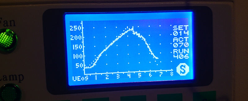
Meawhile I test the heat distribution. Was very surpriced that heating is so terrible in space. If measure the temperature in center it is close to set but on right it is +20C and on left it is -20C. i am talking about 7-10cm on each side from center.
So the reason is clear, in my owen 09/2015 have very nice fan (35mm deep) that move even on min no 1 and make much flow to cool down the left side. The rotation of the fan produce 70 to 30 flow on left side and as well not help the way is holes for fan done to chamber. This produce the moving of the heat from left to right.
Maybe production changes and they use better fan and now the regulation in FW is too raw for this type of fan,
@janekx
Are you using the “improved” firmware ? which uses the fan at the rear to attempt to circulate the air ??
Perhaps this is a bad idea.
This blog has a lot of modifications to the oven
https://theembeddedworkshop.wordpress.com/my-projects-2/arm-projects/
I’m also sure that someone fitted a separate internal fan, a bit like the fan inside a cooker oven.
But I can’t find a link to that website :-(
I will read the other posts and see if I can find it.
Yes improved fw i use. I found the small fan in the chamber in fw issues as link. Look like better idea, then flowing cool wind in to the Owen
Can you post the link, as I think it may be the only way to actually get this oven to work correctly ;-)
Thanks.
I recently bought a T962 and applied the mods described here. Very nice work!
I found a small issue with the gerber files for the thermocouple interface: two of the address lines of the 2nd MAX are floating, whereas they should be connected to ground.
Another small issue with the improved FW is that setting the TC offset to -10 or lower crashes the FW. This can be fixed by changing the corresponding lines in setup.c to
setupMenuStruct setupmenu[] = {
{“Min fan speed %4.0f”, REFLOW_MIN_FAN_SPEED, 0, 254, 0, 1.0f},
{“Cycle done beep %4.1fs”, REFLOW_BEEP_DONE_LEN, 0, 254, 0, 0.1f},
{“Left TC gain %4.1f”, TC_LEFT_GAIN, 10, 190, 0, 0.01f},
{“Left TC offset %+4.1f”, TC_LEFT_OFFSET, 0, 200, -100, 0.25f},
{“Right TC gain %4.1f”, TC_RIGHT_GAIN, 10, 190, 0, 0.01f},
{“Right TC offset %+4.1f”, TC_RIGHT_OFFSET, 0, 200, -100, 0.25f},
};
However, this is only cosmetics on a very well working system.
Got my T962A last week. PCB is marked “T962a NEW2” – I don’t know what if anything is new about it. We removed all the awful masking tape, cleaned up and put a layer of gold tape over the whole blanket (not genuine tape, the medium price stuff). We used 50mm wide tape and put strips across the blanket placed every 40mm to allow an overlap. It wasn’t clear what to do with that wide flap thing at the front. I searched for pictures and put it leaning back onto the blanket and the smaller part vertical above the draw. We then gold taped over it, sealing the top cavity off completely from the oven, otherwise hot air could rise from the oven into the lid space. Just in case the gold tape got scratched down to a conductive layer, we put 50mm Kapton tape over the back (1 strip) and the front (3 strips) as an electrical insulator. We had a small piece of “Vulcanite” type gasket material left over, about 2″ x 1″. Eventually realized it was probably positioned next to the tube mains wires that penetrates the blanket which is close to the edge, as extra protection and insulation. We put extra gold ntape and Kapton there and it seems fine.
Drilled a 5mm hole next to the SSR and fitted a M5 x 20mm button head screw with loctite 222, crinkle washer and full nut. Torqued up hard and left over night. Next day fitted an 80mm length of 2.5 sq.mm (13 AWG) Green and Yellow striped high temperature wire, soldered to the mains connector earth tab, sleeved with heatshrink, and crimped a ring on the other end and tightened it onto the 5mm earth post. We will do the same with the top and botton panels too so earthing is solid. It’s a shame the manufacturers soldered wires to the tabs that were meant for standard spade crimp terminals.
Unexpected things. I pulled the drawer out after releasing the latches and nearly eended up in casualty. Every single piece of stainless steel in that drawer has raw guillotined edges with a really nasty burr. I deburred it all round. Was just about to put the draw back when I noticed the handle hanging at an angle – one of the screws had let go. And of course to get at the screws you have to disassemble the hollow sandwich front. Luckily it is only 6 screws and a battle with the dreaded ceramic wool. Removed and discarded handle screws which were too short and replaced them with M5 x 10mm screws and Loctite 222. Strongly reccommend you do the same, you really don’t want the handle to fall off when you are removing a board.
PCB board. Took loads of photos of the board in-situ so we knew for sure how to put it back together. Rough sketched the connector positions and their polarity. Named them on the sketch and same name on Dymo tape on the wire. Don’t undestimate that delicately applied hot melt glue. I know it’s a precision work of art, but it has to go. Be really careful you don’t rip wires or pull delicate 2 way connectors off the board. Be particularly careful with the 4 thermocouple wires. Removed the 5 screws and fibre washers and released the PCB. Don’t lose the piece of insulating card under the board. With 8 holes and 5 screws you may like to make a not of what goes where before removing them.
With the board removed, I heatshrink sleeved part of the middle leg of a DS18B20, bent it forward then heatshrink sleeved the outer two legs together and shortened them a bit. Used a scalpel to remove the green solder resist between the terminal block and fron of PCB then tinned it. Held the DS18B20 with the flat against the terminal block and legs touching the bare copper patch. Soldered the outer two legs to the PCB ground plane where we scraped it. Superglued the DS18B20 flat side to the terminal block. Soldered a thin piece of wire to the middle leg, heatshrinked it, then superglused the heatshrink back to the device body to give the leg and wire a bit of support. I soldered an 0805 size surface mount 4K7 resistor to the bottom two pads of the unused devices, then soldered the wire from the middle leg to the right end of the resistor, as shown in :
https://raw.githubusercontent.com/wiki/UnifiedEngineering/T-962-improvements/images/tempsensor-mod.jpg
Before flashing the software, I decided to fit the programming stuff in the case so I didn’t have to keep taking the lid off. I used an FTDI 3.3V USB to Serial adapter lead, part number TTL-232R-3V3. This has a six pin molex-type female plug on it, which I eventually removed so may as well have bought the TTL-232R-3V3-WE which has bare wire ends. To that end I fitted a Lumberg SV60 screw locking 6 pin DIN plug, wired as :
1. BLK GND 0V
2. BRN nCTS IP
3. RED VCC_5V OP
4. ORG TX OP
5. YEL RX IP
6. GRN nRTS OP
NOTE – that red pin 3 is FIVE VOLTS and could kill your PCB if it touches it.
I wired a normal 5 pin 0.1″ female molex header. If you hold the pcb in your hands, with the ISP plug at the bottom, then pin 1 is on the left and pin 5 on the right.
1. n_ISP (ground during reset to enter ISP mode)
2. n_RESET (ground to reset)
3. TXD0 (output, join to DIN socket RX)
4. RXD0 (input, join to DIN socket TX)
5. GND (not Earth, power supply 0V)
I fitted the Lumberg KFV60 6 pin screw lock DIN socket to the case with an LED beside it, then a toggle switch between n_ISP and GND and a push-button switch between n_RESET and GND. I had an LED with built in resistor so I put that next to the DIN socket and wired it between GND and DIN socket +5V, so it illuminates when the FTDI cable is plugged in and powered. Hey, you have to put a blue LED somewhere. So, near the front there is, just behind the small fan on approx 30mm centers – DIN socket, LED, ISP switch, Reset push-button. Whatever you do, don’t try to drill holes in thin steel bigger than about 3mm or 1/8″ diameter, they will get stuck and create horrible burrs and non-round holes. Use a drill to make a 2mm (5/64″) diameter pilot hole, then open up with a cone drill (aka step drill). Those that increase in 2mm steps are much harder work in steel than those that increase by 1mm. They do a good job and also deburr the front of the hole. You will have to deburr the backs of the holes with a hand deburring tool.
So far, we’ve had a quick test of the ISP switching circuit. With the machine on, at any time change the ISP swicth so it is closed and press the Reset button briefly, then put the ISP switch back to normal. The screen changes to having a (partially incomplete) white line/area at the bottom and awaits connection on the RX/TX lines. AT any time dab the Reset button and the machine goes straight back to normal power up screen. Annoyingly, the main fan and heater can power up during ISP mode but I understand that is fixed in the UnifiedEngineering firmware so you won’t have to suffer it for long.
Flashing the new firmware is my next job, I’ll try to write up a bit about that when it’s done.
Error in schematic?
I think there is an error in the PDF schematic from the wiki, entitled T962A REV 0.1, 3/7/16 8:52PM. It involves the HEAT and COOL lines, I think they are back to front, and the pin numbers are shifted by 1. I’ll try to explain.
The flashing wiki explains about the fan and heat coming on during ISP and to put a weak pullup on P0.8 and P0.9. According to the LPC2134 datasheet, P0.8 is pin 33 and P0.9 is pin 34. If I trace my PCB, I can see U9 pin 1 tracked to the CPU pin 34 and U9 pin 3 is tracked to pin 33. This contradicts the pin 32 and 33 shown on the schematic. Also, I think that makes the labeling of HEAT and COOL reversed. Something is wrong somewhere, probably me!
Schematic also shows U9-10 (buffered P0.8) driving the Fan triac through R8 and the Heater SSR through the Heater socket. U9-12 (buffered P0.9) only seems to drive the unpopulated U2 triac and the LED. As a cross check, my PCB seems to be tracked as follows :
P0.8 : U13-33 to U9-3, U9-4 to U9-11, U9-10 to R8 and…
P0.9 : U13-34 to U9-1, U9-2 to U9-13, U9-12 to R6 and…
I know this page and comments have aged a bit, but I was wondering (now that this has been out in the wild for a few years) if there is any consensus on which oven is the best performer with the above mods and new FW between the T-962 and the T-962A? As in, if you had to choose over again, which one would you choose and why?
Hi guys,
I succesfully made the modifications and finally I can say “bye bye” to that original awful controller.
First of all I want to thanks very much to everybody has worked to this project and shared to the community.
Then I’m here to give my 5 cents.
After some measurements with another tehrmocouple thermometer, I have realized thet the real temperature in the reflow area is much different from that one measure dby the oven thermocouples, because they are much distant.
So i’im doing some experiments.I hav epulled out the two thermocouples from their original locations and found a way to bring them on the plate.
Need some tuning now with offset and gain parameters. Also need to be careful not to damage the thermocuoples when you open and close the drawer. Also you sacrifice some space on the drawer for the location of the thermocouples, fixed on a small PCB.
But now you have a real measurement point….
I have some pictures but don’t know how to post them here.
Any comment is appreciated,
Simply post links to your images wherever they are hosted online.
You’re right. Here they are https://1drv.ms/f/s!Ak1xBLnncsa5lZtXyGgW-2lpOCKADA
How come no one has tried the T962C model???
Hello guys,
I bought T962 while ago and I did changes like replace paper tape, add cold junction and replace firmware.
I did some temperature profile measurements and it was ok.
But today I turn on my oved and nothing. Backlight on display only blink at start and then is off.
I did some measurement like voltages (3.3 is there) and xtal (is running at correct frequency) and that’s correct.
Did you have guys similar problem? Or have you some hints what could be wrong?
Thx
Ok guys , problem solved!
Pull up resistor on eeprom SCL line was open. (shitty Chinese parts)
After replace all is working fine again.
Hi guys,
Just opened my T962C. I would like to do all necessary updates. Will post them here. Have made already some pictures, but dont see how can I add them here.
Pictures of T962C
https://onedrive.live.com/?id=D66A04E947BC5C86%21105&cid=D66A04E947BC5C86
https://onedrive.live.com/?id=D66A04E947BC5C86%21112&cid=D66A04E947BC5C86
New PICs
Stuffed the bottom holes with insulation.
Added internal circulation fan.
Added 4 pcs of 400W 40cm long rod heating element.
Sorry ! Added 2 pcs of 400W 40cm long rod heating element.
@zszaboka
Its not possible to access that one drive account without logging in.
You’ll need to change the permissions or make it public
And by this link ? https://1drv.ms/f/s!AoZcvEfpBGrWcBbPkzpI5N8SgvE
Hi,
Before starting with the modification I would like to know if it’s possible to adjust the wave profiles from the oven as I’m using SN96,5 Ag3 Cu0,5.
Thanks!
@zszaboka Your mode seems to be the good one since the oven lacks power and I suspect the heating elements should be placed head to tail to annul the temp gradient from left to right – or is this really the 35 mm fan that cools the left part of the device? Could you give more details on how you added heating elements? Do you still use the same Triac to power them, without additional heat-sink? And what about replacing the (cheap) heating elements with higher quality / power ones? Finally is this much better (heating speed) with this 800W more and is it safe / does not heat the apparel too much?
@zszaboka It seems that there is a problem: I have just finiished the modification. If I press F1 and going back with S then the coldjunction temperature is jumping up to 85 degree Celsius and the fan begins to run. The only way to get out of this is to turn off and on the oven. May be there is a software bug or have I done something wrong?
Just ordered my T962 and am preparing to apply most of the mods described. I’ve downloaded a et of controller schematics which say they are for the T962A Rev 2 (dated 4/3/16) – do both ovens use the same controller?
I’m thinking of adding an oven fan underneath the heating elements, this to run continuously during the reflow cycle so as to even out temperature. Is this a worthwhile mod?
I’ve tried and failed to find new firmware files on Github, I need major help please to navigate though to the latest version (or indeed ANY version!) Would I be looking for a .hex file for the flash operation or does this need to be built from the source files – don’t have nearly enough experience to do that with “C” applications!
Found my way around Github to download .hex files at last!! Now need to correlate versions with hardware mods and capabilities.
Received my T962 oven a few days ago – this one was marked “Eco-Worthy”. It had the usual masking tape”insulation” and the standard isolated earthing connection! The masking tape was replaced by Kapton tape and earthin made good by removing paint under mains socket and transformer mounting screw, followed up with shakeproof washers and additional earth wires from the mains socket.
A new earth wire was run from the mains socket through the mains cable sleeve to a control pcb mounting screw. This effectively earths the whole of the top of the case. The control electronics is presently isolated from ground, but after studying the control board there appears to be no earthly reason for this to be so (sorry about the pun).
All mains wiring connectors were removed from the pcb, and for safety reasons this was powered from a stabilised 9volt supply whilst the mcu was flashed with new software (V0.4.1) downloaded from GitHub T962 project. Flash Magic was used to perform the download which, at 57600 Kb took less than a minute.
It is important to realise that USB to TTL converters have the data OUTPUT pins marked as RXD, and that this should connect to pin 3 on the ICSP connector. Data INPUT from the controller ICSP (pin 4 ) connects to TXD on the converters. Flash mode is entered by powering up with ICSP ( pin 1) grounded, then removing the ground to run the bootloader.
The only hardware modification to the controller board was the addition of an Arduino temperature sensing module to read cold junction temperature. There are three convenient pads on the pcb to which connections can be made. Next job is to calibrate the thermocouples using an external K type meter. Should be fun!!
No one has even mentioned there is masking tape wrapped round the ends of the heating tubes…
Plus the heating bulbs are in two banks of two heaters each in series therefore each bulb is 110v 300watt —
like rocking horse droppings, so I am going to change to a parallel system so I can use 4 x “AC 220V 300W Quartz Heater Tube Infrared Heating Element Pipe 27cm”
Will post here with the results…
I just bought a T962A+ and it is substantially different from the T962A. I guess it’s fairly new, don’t see much on the web about it. They seem to have fixed a number of the problems I see reported. Still has the stinky masking tape though.
Looking at the control PCB, I see it has a cold junction component. The uC is an STM32F103. It has a USB port and a PC app so you can download custom temperature profiles. The timing is accurate. The fan blows out, not in. Hmmm, what other complaints were there? I’ve only played with it for an afternoon, the bulk of my problems were applying paste and placing components by hand.
Anyone have any more information?
Oh, I forgot to mention the ‘A+’ is 2300W. I think the ‘A’ is 1500. It has 2 thermocouples, not sure if the older ones had that. There’s room for a large panel, maybe 14″x17″. The display reads about 5degC higher than my Fluke, probing near the front. The internal thermocouples are in the middle (front to back), 1/3 and 2/3 across.
Just followed the instructions provided to add the 1 wire thermometer, replace the masking tape, and reprogram the uC. System works well, although it fails to boot about 1/3rd of the time (so I cycle power until I see a successful boot). I am seeing substantial offsets (like >10C) between the thermocouple readings, so I’m glad that offset adjustments were provided. All my connectors were glued in place, so I didn’t unplug anything to make the mods. This was a brand new T962 (the smallest version).