In this installment of Scope Noob I’m working with Direct Digital Synthesis using a microcontroller. I was pleasantly surprised by some of the quirks which I discovered during this process. Most notably, I had a chance to look at errant triggers solved by using holdoff and a few timing peculiarities introduced by my use of the microcontroller. Here’s a video synopsis but I’ll cover everything in-depth after the break.
Direct Digital Synthesis
DDS is a method of creating analog signals from a set of digital inputs. I was inspired to give it a try after watching [Bil Herd’s] post and video on DDS. But he was using programmable logic and I thought I’d give it a try with a microcontroller.
R/2R Ladder
A simple R/2R Ladder is the key to this experiment. It’s a network of resistors in a 1:2 ratio with one another. I would recommend targeting 10k and 20k resistors; what I had handy was 500 and 1k which worked well for this. Eight bits of the microcontroller drive the digital inputs of the ladder, with a single output that is an analog voltage between 0V and Vcc.
My code examples for each of these experiments are available in this repository. The code was written for an ATmega328p (which is what the Trinket Pro is rockin’) but it’s vanilla enough to easily port for anything. My first run is a simple ramp signal using code that loops through an 8-bit variable and is also used as the output value. When it overflows the ramp begins again.


uint8_t counter = 0;
while(1) {
  PORTC = counter;
  PORTB = counter >> 6; //Shift the counter so MSB is on PB0 and PB1

  ++counter;
}
Notice that there are several yellow blips on that ramp signal. I’ll get into that in a little bit, but with a working “hello world” for the DDS I wanted to refine my methods by using hardware interrupts. Setting up Timer2 at the system clock rate of 16MHz with a counter resolution of 256bits still allows me to generate a frequency of 440 Hz:

ISR(TIMER2_COMPA_vect)
{
  static uint8_t counter = 0;

  PORTC = counter;        //Set PORTC
  PORTB = counter >> 6;   //Set PORTB

  counter++;
}
It is worth noting that those blips in the signal are still there, just a bit harder to see on the above screenshot. As you can see, this signal is clocked at 438Hz, quite close to my target of 440Hz. That frequency is an ‘A’ in pitch. I figure I might morph this into an audio project eventually and if that happens I’ll wanted a signal that sounds better than a ramp wave does.
I Saw the Sine
This setup is well prepared for generating more interesting signals. All that’s needed is a better set of data to push to the ports than an incrementing counter. The most common way of doing this is to use a lookup table. I found a website that will generate sine wave values based on your parametric needs. I loaded up one with 256 bits of resolution so that I could still use the counter overflow as the index of the array.

ISR(TIMER2_COMPA_vect)
{
  static uint8_t counter = 0;       //Declare static this will only be instatiated the first time

  PORTC = sine[counter];            //Set PORTC
  PORTB = (sine[counter++]) >> 6;   //Set PORTB and increment the counter
}
 That’s quite a pretty curve, but now we’re still seeing those signal anomalies and there’s a new issue. When I zoom in on the waveform I sometimes get a double signal. This looks like a sine wave inverted and overlaid on itself.
Not knowing what caused this I pinged [Adam Fabio] to see if he had any insights. He mentioned that it’s probably an issue of the scope triggering when it shouldn’t be.
The DS1054z that I’m using has two settings in the trigger menu that may be able to help with this. The first is a toggle that tells the scope to ignore noise when triggering. I was able to get this to work a little bit depending on my timebase and trigger voltage but it wasn’t a sure fix. The other option was Holdoff.
Learning about Holdoff
Holdoff is a feature that allows you to dial in a “blackout” window where the scope will not trigger. The best discussion of the feature that I found is [Dave Jones’] video regarding holdoff. He shows several use cases but mine is one of the easiest. I know the timing that my signal uses and I calculated that a holdoff just a bit longer than 2.1ms should be enough for the scope to trigger at the start of each period.
Splitting Microcontroller Ports

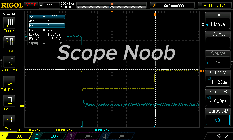
It’s finally time to figure out what’s going on with those blips in the signal. Here you can see that I’m measuring one of those blips which is about 1.024 us wide. That’s actually quite a lot and so I started probing around with channel two to see what’s going on. Very quickly I figured out that the blips always occur between bit 5 and bit 6 of the R/2R ladder.
In this case I’m really glad I used the Trinket Pro because otherwise I wouldn’t have had these blips to play around with. Normally I would use all eight bits on a single port but this board doesn’t offer that. Because of this I’m using PC0-PC5 and PB0-PB1. The blip occurs because of latency between writing PORTC and writing PORTB.
The C code that I wrote in the Interrupt Service Routine is very concise and beautiful C code. But the assembly generated from it shows why I’m getting large blips:
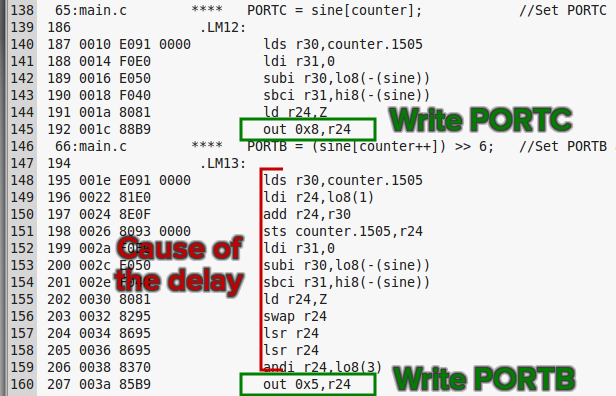
You can see that there are numerous instructions between the write to PORTC and the subsequent write to PORTB. This was simple to trace down because of my probing using the scope. The best part is that you don’t have to resort to writing your own assembly, instead you can just craft your C code with timing in mind:
ISR(TIMER2_COMPA_vect) {
  static uint8_t counter = 0;

  static uint8_t prewindC = 0;
  static uint8_t prewindB = 0;

  PORTC = prewindC; //SET PORTC
  PORTB = prewindB; //SET PORTB

  prewindC = sine[counter];
  prewindB = (sine[counter++]) >> 6;
}
In the interest of brevity, here is the resulting assembly and the new blip measurement (click to enlarge):


The result of coding with the microcontroller in mind shortens the blip in the signal by about 5 times! It is perhaps possible to further reduce this by half by using in-line assembly as there is still one instruction call in between port writes. But I think this a fantastic example of an oscilloscope saving you time in troubleshooting.
A Rant about Microcontroller Choice
 Obviously working with a bare chip rather than a breakout board would have allowed me to use 8-bits on one port. But lets assume you were required to work with this restriction. With most 8-bit controllers you’ll hit another gotcha that I experienced here: to write to PORTB using one instruction I have to blow out the entire PORTB register even though I’m only writing 2 bits.
The reason for this is that you cannot write both digital 1 and digital 0 to the port using bitwise instructions. The best you could do is to first set your target bits to a known value, then to use a second instruction to write the bitwise values you seek. Obviously if you’re dealing with timing this is not optimal.
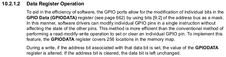
Most 32-bit microcontrollers (and some 8 or 16 bit varieties) have a workaround for this. Above is a paragraph from the TI datasheet for a TM4C123 chip. It shows that this processor allows single-instruction write without overwriting the entire port because it has a mask feature in the upper bits of the register. You can use an assignment operator and only the bits set in the mask register will be affected.
Homework
I don’t have a firm plan yet for next week so I can’t tip you off about the topic. Help me along by suggesting an area for me to explore by leaving a comment below.


This series will be of great value to me, especially as a fresh owner of the very same scope model.
Funny that, I should be getting one for christmas too!
Unsurprising really ‘cos its the same scope HaD helped popularise a little while ago, due to its ability to unlock loads of cool features and improvements.
***On that note, does anybody know where we can find a working riglol hack page? It used to be on 3owl but has since been pulled.
Can anyone explain this line of code? Where is the variable gt declared? Is the ampersand being used as a bitwise AND or address of operator in each line? How is “6;” a line of C code?
PORTB = counter >> 6; //Shift the counter so MSB is on PB0 and PB1
The >> operator is a bit shift operation.
For example if counter = 0b11111100, counter >> 6 is 0b00000011
For more in-depth I always enjoy [Dean Camera’s] tutorial: http://www.avrfreaks.net/forum/tut-c-bit-manipulation-aka-programming-101
Those “>” you see are from browser rendering “>” not part of the code. I read that too (using Opera) earlier, but they seemed to be corrected. It was distracting.
Yeah, sorry. I think the wysiwyg editor of WordPress sometimes blasts out the >> when a post is edited. I fixed those shortly after this was published.
Great segment! How about capturing transient signals? Seems a logical next step.
Cool article. A scope would definitely help with my Trinket project ( http://hackaday.io/project/3439-dafunc )
Although I’m hoping to use both and R2R DAC and a low pass filter for more outputs
Another way to minimise the glitch would have been to put the extra bits on the LSB end of the L/2R ladder so any delays in the update have less effect to the resultant value as those different bits represent a smaller voltage change.
Taking a simple case where the value increments by ‘1’ (what should be 1/256 of Vcc – 0.004Vcc), changing from b00000011 to b00000100, looking at the bottom 3 bits could result in a sequence 011->111->100 or 011->000->100 (depending upon the port writing order) which only equates to a difference of voltage delta of around 0.012-0.016 of Vcc.
However, as in the current implementation changing from b00111111 to b01000000 takes potential transitions of b00111111->b01111111->b01000000 or b00111111->b00000000->b01000000 which equates to changes of between 0.246 of Vcc and 0.5Vcc! (see the massive glitch in the [Mike]’s pictures).
Oh, and my example isn’t even taking a worse-case example (where one sets of bits transition between zero and all set while the other goes in the other direction).
I thought about this, but I figured that would cause the delay to occur more frequently. I assumed that would be worse than having it on the MSB end but didn’t do any testing to confirm.
What about adding capacitors to the two spare bits as a delay, and switching them first?
I guess it depends upon the application (and what circuitry you place on the output) as, yes, if you are stepping through each value then you do get more glitches (albeit somewhat smaller) but any changes are at least always closer to the intended value.
If you know that you’d rarely use the MSB values then it may be nicer to go with a rare, large glitch but, in a scenario where you’re hopping all over the place, accuracy may be more valued in which case having them in the LSB might be nicer.
I was just thinking about an example application: audio DAC – as it’s audio, it means there’s a frequency limit so one could pick a suitable RC network such that it ‘bridges the gap’ when the values jump (effectively a low-pass filter). It’d be an interesting experiment to see (well, hear) what the difference between the four configurations would actually sound like (MSB vs LSB and with/without low-pass filter – actually what the highest frequency that can be achieved as they shouldn’t need the same RC filter).
I think you would find that having them on the lower significant bits would be better even if they happened more frequently. Also you are correct in that you can eliminate that extra load between storing to the two ports if you wanted. Third, another option would be to latch the entire eight bits with an eight bit latch and clock it all out at once.
Really what you want is either to have all of the pins on the same port (these ports are 8 bit, are they not?), or failing that, some sort of latch in between the DAC and the µC. Most R2R DAC ICs have a latch exactly for this purpose.
A latch would work in this case as an addon but not the single port on this specific board. I didn’t bother with looking at the schematic but the author does say a full port isn’t available.
If designing a board from beginning to end, those are suggestions to seriously consider. If you’re working on existing hardware those become a wishlist item.
A way to fix this in hardware, of course, is to use a latch, which allows you to update the bits at your leisure, then toggle them all at once with the latch pin.
simpler/smaller way to do it, avoiding unnecessary ‘static’ values:
val = sin[counter++];
PORTB = val >> 6;
PORTC = val;
Also, if you’re getting serious about DDS, instead of recalculating the SIN table for each frequency, you can take a similar approach to what actual DDS chips do: have a phase register. Something roughly like this:
int frequency = 123;
int phase = 0;
while(1) {
phase += frequency;
output(waveform[phase >> 8])
}
This assumes 16 bit ints for phase and frequency, and an 8 bit waveform table. Different bit widths, and interpolating between samples, are left as an exercise for the reader. ;)
The more I see the 1054Z in action, the more I wish I hadn’t bought my 1102E last year and had waited for the new one. Of course, I had no way of knowing that Rigol would be putting out such an improved scope at the same price point. Oh, well. My scope does almost everything I need it to, and it’s a heck of a lot better than the Tektronix 453 it replaced.
Please keep this series coming! Even though I have been using scopes here and there since I was a teenager, I learn something new with every issue.
Same with me, it hurts :/
But before that I worked with ugly workaround and Led’s to guess stuff, with it I was in control of Time.
thats what Ebay is for, sell current one, but new one, simple
The next step would be to analyze the waveform using the scope’s FFT. Look at the harmonics content as you crank up the frequency of the DDS and/or change the waveform types. Also would be interesting to see the upper harmonics before and after the change in the code. That glitch would show up as a small peak at the interrupt loop frequency.
This is what [Bil Herd] suggested. I’ll check into it. Thanks!
“generate a period of 440 Hz:”. Period is a time interval, Hz is frequency.
You just beat me to that…. the period would be 1/440 second or about 0.00227 seconds.
Right, sorry for the slip up there.
I _think_, having never tried it before, that defining the ‘prewind’ variables as register (register uint8_t prewindC = 0;) should eliminate the extra load between the two outputs. Obviously you’d need another set of static variables, and there would still be a single clock cycle between the two outputs being set.
Of course, for a smooth function a simple RC filter could help enormously.
Just removing the ‘static’ should be enough to get the compiler to use registers. See the code I wrote earlier.
Use a look-up table for a full period of the sin-values, that saves time. You may even store only the values for a 90-degree segment if you than change count direction and value sign. That saves memory.
Interesting idea. If I run into memory constraint issues with my project I’ll have to look at that.
FYI: The undershoot of the blue trace (first scope trace, zoomed in) is an indication that the rise/fall time of the signal is too fast to be using the long ground clip on your scope probe. Reduce the loop area of the ground connection (with a short grounding spring attachment on the probe) and you’ll see it disappear.
Don’t know what you’re driving next in your signal chain, but you’ll probably end up buffering the R2R DAC’s output which is a great time to lowpass the analog signal and make it even “analoger”.
Of course, then you’d never have seen your glitches or fixed the original problem…
But you used to have to do this in the bad old days with DAC chips that had horrible switching transients.
This is also a good demonstration of what a compiler does to your C code. It isn’t required to maintain the order or timing – it only assures numerical equivalence of the output. You try using the ‘register’ hint to persuade it to use two registers. Ultimately it doesn’t have to listen as that’s only a hint. To have assurance of the timing, and to have less compiler/mood dependent code, you’ll likely need to use an inline assembly block for the final assignment to the port. The ‘prewind’ shouldn’t be necessary and you should avoid static variables where possible. Static variables typically require significant additional overhead. Here you introduced two more to reduce the number of operations between assignments, but there would appear to be better options… I’m a fan of the column; keep up the good work!
err that should read “you could try using the ‘register’ compiler hint to persuade it to use two registers”..
The ‘register’ keyword isn’t going to help as long as the variables are declared ‘static’. The static register combination is not supported.
I lurk here often, two or three times a day, to be exact, but I have never entered a discussion. But in this case, I thought I’d offer some information that could make life easier, when looking at unstable waveforms with an Oscilloscope.
Reliably triggering on complex (and even basic sine waves) waveforms is a long standing issue. With the advent of microprocessors and microcontrollers, a simple method of syncing on a waveform is to use the external trigger function of your scope.
Basically, when your DDS waveform reaches some point, tell the microcontroller to toggle an IO line on the microcontroller. This toggling IO line becomes the external trigger input to your Oscilloscope. The DDS IO trigger output can happen anywhere within the waveform, as long as it occurs at the same point in the waveform – EVERY TIME.
The theory is, with the internal trigger, there is a slight delay between the time the waveform activates the internal trigger and when the scope begins the trace on the scope display, the waveform may have a lot of noise riding on the waveform, causing jitter when seen on the scope display. And as you have probably seen, a problem that occurs is that, the current sweep isn’t always finished being displayed on the scope, before the next internal trigger level has been reached by the incoming waveform and causes a mis-triggering of the horizontal sweep.
The idea is, you want to establish a trigger sync that toggles the IO pin at the exact same point in the waveform. By toggling (low to high on one sweep, high to low on the next sweep, low to high on the sweep after that, etc…) you get one trigger signal every other waveform, giving the horizontal sweep before the next incoming trigger is generated.
The time along the waveform where you actually toggle the IO pin isn’t so important, as is consistently triggering the IO pin at the exact same place in that waveform.
So, say you are generating a sine wave with your DDS system. A good place to toggle the IO bit might at half count (0x7F), especially if you are planning on offsetting the DDS generated sine wave to a +/- P-P waveform That is, rather than being 0 to 5 peak to peak waveform riding totally above Ground, you offset the sine wave so that it becomes a conventional +/- 2.5 VAC P-P waveform
The reason you toggle the IO line is that, by it’s very nature, the trigger needs to be a lower repetition rate (read, lower frequency) than the signal you are observing. So toggling ensures that every waveform is looked and so, the toggling the IO line ensures that conventional synchronization requirements are met for a consistent and stable waveform.
So, if, as with an AVR, you are looking at a sine wave being generated by an 8 bit R2R ladder network connected to the IO pins of one of the 8 bit IO ports, the range of values is 0:255. If you want to trigger at what would will eventually become a true AC zero crossing, check the IO data feeding the R2R ladder for 0x7F. If not, toggle the IO line at 0x00 or where ever you like – as long as you toggle the IO line at the same place within the waveform.
I hope this helps.
C.W.L.
How do you get the assembly of your C code?
I miss these posts. Keep more coming! I just got a 1054z, still figuring out how the thing works. Your posts helped a lot.
The artifact looks like underdamped oscillation. Probably stray capacitance/inductance. Experiment with physical layout of the parts on the breadboard. Easy thing to try before jumping into ISR voodoo.