[Brett] was looking for a way to improve on an old binary clock project from 1996. His original clock used green LEDs to denote between a one or a zero. If the LED was lit up, that indicated a one. The problem was that the LEDs were too dim to be able to read them accurately from afar. He’s been wanting to improve on his project using seven segment displays, but until recently it has been cost prohibitive.
[Brett] wanted his new project to use 24 seven segment displays. Three rows of eight displays. To build something like this from basic components would require the ability to switch many different LEDs for each of the seven segment displays. [Brett] instead decided to make things easier by using seven segment display modules available from Tindie. These modules each contain eight displays and are controllable via a single serial line.
The clock’s brain is an ATmega328 running Arduino. The controller keeps accurate time using a DCF77 receiver module and a DCF77 Arduino library. The clock comes with three display modes. [Brett] didn’t want and physical buttons on his beautiful new clock, so he opted to use remote control instead. The Arduino is connected to a 433MHz receiver, which came paired with a small remote. Now [Brett] can change display modes using a remote control.
A secondary monochrome LCD display is used to display debugging information. It displays the time and date in a more easily readable format, as well as time sync information, signal quality, and other useful information. The whole thing is housed in a sleek black case, giving it a professional look.


If you are absolutely sure your 7 segment displays will never need to show anything but a 0 or 1, you could drive them directly with greatly reduced wiring. Just connect the right side segments together with one connection. Connect the top, bottom, and two left side segments together with another connection. Power the first to display 1, power both to display 0. 21 digits = 42 wires. Then figure out some method to multiplex those 42 signals to reduce it further…
In this case the flexibility of having all segments wired in is good for future implementations, you might just get tired of decoding binary and want it to say something else altogether.
I agree that the flexibility to change the functionality is probably the way to go. I just wanted to make the point that sometimes if you consider what functionality is not needed it can greatly change your circuit requirements.
Was thinking along these lines, myself… OTOH, it sounds like the builder didn’t have 7-segs already… so making it future-compatible like Nova suggests kinda makes sense. OTOOH, someone with, say, bags full of old (dim) 7-segs, no idea what to do with ’em all, but needing to do *something*, and a tendency to use once-highly-useful things in ridiculously-simplistic ways might find this quite handy to consider… And somewhere in reading your response might be inspired to also consider that some digits needn’t be wired-up as changeable at all (e.g. bits 5 and 6 in the hours could be wired straight-to-‘0’)… might even be worthwhile to throw in that 8th bit, just for the heck of it. And, 42 wires for 21 digits is great, but those “1”s could be wired-up permanently… then it’s at-max 21 changeable bits (fewer?)… lotsa microcontrollers out there that could handle that straight. I dig it.
(heh, and a “0b” in front, just to use up some more early 80’s displays)
Each module of 8 7-segment displays only use 3 wires. The wires loop to the next display etc so in all I only need 9 wires to connect all 24 digits including the decimal points. Using the Arduino software I could have added normal decimal, Hex or even a message display. I think you can add up to 5 modules of 8 displays off the Arduino.
Can you chain all three rows and run them all off only three wires?
To clarify my original post, I meant that wiring for just display of 0 or 1 would reduce the wiring compared to a typical design that would multiplex all the digits and segments in some sort of row/column matrix and drive them directly.
Ah yeah I see what you mean yes that would reduce the wiring compared to a typical design.
You can run all three rows (I think max 5) off just 3 wires. You go in 1 side of the module and out the other and daisy chain the modules together. Each module has it’s own MAX7219 IC and this is controlled very simply by the Arduino via an added library.
The MAX7219 can also drive dot matrix displays as well via the same library. In my code on my web page look for the ” lc. ” commands these are the MAX7219 library controls.
Beautiful build. Very nicely done.
Yep, thing of beauty.
How about some proof reading? “. [Brett] didn’t want and physical buttons on his beautiful new clock”
In the middle of Back to the Future as I read this post lol
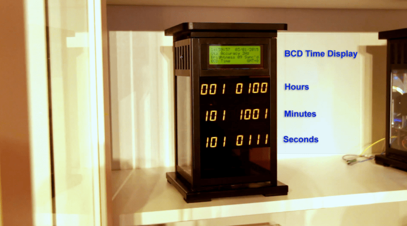
Stange. The debug screen shows 14h59m57, but the binary shows 20h59m57.
The debug shows also GMT+0.
Best guess is there is another +4 setting somewhere, is this a Russian maker?
+6 I mean. Man am I bad in head calc early in the morning. India then.
Binary shows 14h59m57 same as LCD screen. Display is in BCD mode. GMT+0 is correct as the clock is in London (GMT) and it’s winter so summertime is not active.
Why are there an infinite number of binary clocks but I never see a hexadecimal one?
And there even exists a ‘hexadecimal time’ https://en.wikipedia.org/wiki/Hexadecimal_time although that might be a bit much.
You can quite easily make this clock display in HEX as well and I did think about it. Not a HEX clock as per your link but a HEX display of decimal time. The problem was using the 7-segment displays I had purchased the letters in HEX show as a mixture of upper and lower case that I thought would spoil the look of the clock.
Maybe an idea for the future using a DOT matrix display……………….
Oh, nicely done btw, I like the enclosure, it’s become rare on HaD to see enclosures at all let alone one you can put in a living room.
Thanks Whatnot. I have to put my clocks into proper cases in order to get them “approved” by the wife!
Love the clock Brett !
Would be great if the clock had the option of a minute tick sound and hourly chime, like the clock in the background :)