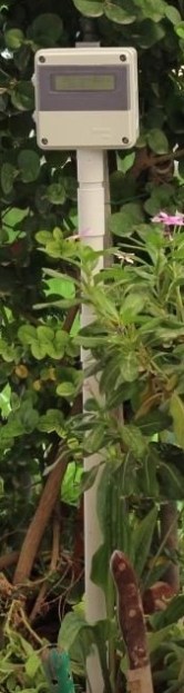
 [Husham] not only likes his electronics projects but clearly enjoys documenting them as well. He’s written a nice Instructable on a Temperature Data Logger that he has built and thankfully makes his code available for others to use. The end product is cleanly designed and made for weather-proof outdoor applications.
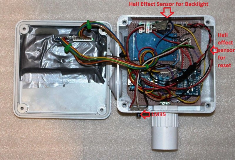
As you may expect, the brains behind this operation is an Arduino. It is coupled with a Real Time Clock to maintain accurate timing as well as an SD Card Module which is used to store the data collected. In this case, the temperature is read by a LM35 temperature sensor and that value, along with the time, is recorded to a .csv file on the SD card in one minute intervals.
There is also an LCD screen that displays the date, time and current temperature. To save battery life the LCD backlight is normally off. It can be turned on using a magnet that interacts with a hall effect sensor on the top of the case. This worked so well that [Husham] installed a second hall effect sensor on the side of the case that resets the Arduino. Speaking of the case, it is a weather proof PVC electrical box with a conduit adapter installed on the bottom side. A battery pack made up of two used laptop cells housed in a piece of conduit supplies 7.2 volts to the Arduino and other components. Unfortunately, there’s no word on how long the battery pack lasts. Once the data is logged, the SD card can be removed and the .csv file opened in spreadsheet software to make a graph showing temperature change over time.


The problem is the LM35 used this way can be + or – 2 degrees out adding the variances on the device and on the arduino chip. That means it can be as much as 4 degrees hotter or colder than what is recorded . There are a thousand different devices on the market that do the same job better and for less cost probably. How old is this? I was playing with these 4 years ago!.
The datasheet says the LM35 has a “typical accuracies of ±¼°C at room temperature and ±¾°C over a full −55°C to +150°C temperature range”. So what exactly do you mean by “used this way …”
You also need to add the errors of the ADC and the reference voltage.
If you wire the LM35 directly to the ADC input you are not using the ADC’s full resolution, as the output voltage may vary, for instance, from 0V to 250mV while temperature is between 0°C and 25°C. You may need to amplify (OpAmp maybe?) this signal to make it Rail-to-Rail.
Uh, for those less informed, would you care to recommend a sensor?
I quite like the digital temp. sensors as you don’t need a separate v ref. The Dallas one wire based devices have been pretty good (DS18B20 and friends…). Or the likes of TI’s TMP102 (sparkfun have a breakout board). Both have Arduino libraries that make them simple to use.
Very simple to use. I made this DS18B20 setup basically by copying sample code. Almost felt to easy.
http://burnt-traces.com/?cat=3&paged=2
Second this with the DS18B20. I actually built the data logger myself when Samir published this last year. With a few small mod’s (Ill dig it out and post it) I added the DS18B20 sensor, just £2 on eBay in a complete probe package. Accuracy is fantastic and its still running to this day! Surviving winter so far in my garden….
I have had a 1-wire temperature sensor setup in my garden for 3+ years (I’m north of Boston). I have a T4-R1-A (w/ moisture coating & under a pagoda ) from http://www.hobby-boards.com/store/products.php?product=Temperature over a long cat5 cable buried in the ground to a DS9490R-P USB to 1-wire adapter. I had to knock a wasp nest out of the pagoda once…
I use thermd (http://www.klein.com/thermd/) + owhttpd (http://owfs.org/) on my server to record & graph it all.
I also had a raspberry pi setup w/ wireless and owhttpd to have a remote version to move around w/o redoing all the cat5.
Anyways, my setup needed a computer running to track everything. This is a very nice build!
DS18B20. Cheap, nice precision and very easy to interface (OneWire). They’re also available with cable and waterproof case for few bucks.
How old is this? Temperature data logging never goes out of style.
I wish Hack-a-day didn’t even have comments. Always sooooo negative.
I take it you are downunder somewhere? Oh the green!
Of course it can be just as good to know how #%*+@! cold it is right now.
What’s the deal with using these breadboard diagrams in place of a circuit and/or block diagram? They’re so hard to read that I don’t bother, and sort of like showing only the PCB layout but without the circuit.
I’ve been needing to get that off my chest. Thanks.
I would like to see something like this under $10 without the LCD
https://www.sparkfun.com/products/9530
It’s not $10 but it sure does make it easy
http://Www.thermoflasher.blogspot.com
That case isn’t “waterproof” it’s got holes for the temperature sensor and for the mount. It’s going to accumulate moisture over time and eventually die.
The holes are at the bottom, so how can it accumulate ?
The title of this article would only be better if it were “Temperature data logger logs temperature data”
Did anyone notice the knife stuck in the ground at the bottom of the field-deployed photo? Tough neighborhood…