It’s a counterintuitive result that you might need to add noise to an input signal to get the full benefits from oversampling in analog to digital conversion. [Paul Allen] steps us through a simple demonstration (dead link, try Internet Archive) of why this works on his blog. If you’re curious about oversampling, it’s a good read.
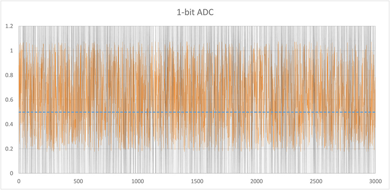
Oversampling helps to reduce quantization noise, which is the sampling equivalent of rounding error. In [Paul’s] one-bit ADC example, the two available output values are zero volts and one volt. Any analog signal between these two values is rounded off to either zero or one, and the resulting difference is the quantization error.
In oversampling, instead of taking the bare minimum number of samples you need you take extra samples and average them together. But as [Paul] demonstrates, this only works if you’ve got enough noise in the system already. If you don’t, you can actually make your output more accurate by adding noise on the input. That’s the counterintuitive bit.
We like the way he’s reduced the example to the absolute minimum. Instead of demonstrating how 16x oversampling can add two bits of resolution to your 10-bit ADC, it’s a lot clearer with the one-bit example.
[Paul’s] demo is great because it makes a strange idea obvious. But it got us just far enough to ask ourselves how much noise is required in the system for oversampling to help in reducing quantization noise. And just how much oversampling is necessary to improve the result by a given number of bits? (The answers are: at least one bit’s worth of noise and 22B, respectively, but we’d love to see this covered intuitively.) We’re waiting for the next installment, or maybe you can try your luck in the comment section.


Instead of noise you could also add the output of a DAC to the input, and cycle the DAC output at the same rate as the ADC input. This would require fewer samples, and result in less noise.
Oversampling works well only with white noise.
Otherwise, e.g. a 50/60 Hz noise from the power lines, there might be fake results depending on the sampling rate and on the number of averaged samples.
I tend to think of audio recording (for music) when the topic of oversampling comes up. With so much equipment with DC/DCs injecting asynch noise into mains, the “noise floor” noise tends to be pretty white.
But I agree with you that for mains hum the situation is different.
The “one bit of noise” thing is fairly simple too:
Let’s say we have an ADC whose resolution is 1,2,3,etc and a signal whose true value is 1.5. If you add one bit of noise to the signal, you’ll get a series of readings between 0.5 and 2.5. Let’s make it simple and say the ones between 0.5 and 1.5 get recognized as ‘1’ and the ones between 1.5 and 2.5 get recognized as ‘2’. The ones exactly at 1.5 can go either way, but will be rare compared to all the other possible values.
Noise is distributed randomly, so if the true signal is 1.5, the number of noise-adjusted values that map to 1 will be roughly the same as the number that map to 2 (and that becomes more true the more samples you collect). When you take the average of the readings, it will come pretty close to 1.5.
If the true value of the input was 1.75, the noise-adjusted values would range from 0.75 to 2.75, and statistically you’d get about three times as many readings of 2 than of 1. The average would come out somewhere near 1.75.
The same basic principle holds for any point between 1 and 2. If the true input value is N times closer to 1 than to 2, a series of noise-adjusted readings will have N times as many 1s as 2s.
With that on the table, the 2^2B thing falls out of the way you have to write the tolerances on the noise-adjusted readings.
If we add tolerances to the noise-adjusted readings, what we really get is a series of “1+/-1” and “2+/-1” values. The average of the base values is still 1.5 (assuming equal numbers of both), but we have to figure out what to do with the tolerances on noise.
We assume the average value of noise is zero.. if it wasn’t, noise would be an infinite source of free energy.. and experience shows that we can take a worst-case estimate on the average of two +/-1 tolerances as +/-0.5.
So.. the average of two noise-adjusted readings taken on a true input value of 1.5 would be 1.5+/-0.5
That’s a problem, because both 1 and 2 are in the error tolerance. Worse yet, our readings for a true signal of 1 would be 1+/-0.5, so the tolerances around 1 and 2 overlap the tolerances around 1.5. That means the average of 1.5 still has a 50-50 chance of being wrong.
If we take the average of four readings, the noise tolerance becomes 0.25, which is much nicer. To write the reading for a true signal of 1.5 another way, we can say it’s in the range (1.25-1.75). The reading for a true input of 1 would be the range (0.75-1.25). Those two ranges only touch at their edges, so we can be confident that a 1.5 isn’t really a 1 and vice versa.
Taking the average of four readings reduced the tolerances enough for us to be confident in a reading halfway between the base resolution, so 1 extra bit of resolution cost us 4 samples. We can write 4 as 2^2*1, take 0.5 as our new base resolution, and do the same thing all over again. In human language, each additional bit or resolution takes four times as many readings. The 2^2B thing is just what you punch into a calculator.
So you are saying noise goes down as the square root of the number of samples – for white noise.
isnt this like a 100 years old and called dithering?
Check!
Except most folks don’t read 100 year old articles, or have a collective consciousness. The old stuff has to be brought up periodically to introduce it to new minds. Even if you already knew about it, it might have been mentally filed away and essentially forgotten; with a little reminder helpful to find new applications. This is a timely post too, since the topic came up in the RF distance measurement comments. I like.
A nice explanation, but I don’t think it’s entirely complete yet from a practical sense.
Any practical ADC above will have at least 2 bits peak sampling noise of its own(Except sigma-delta, but this already exploits oversampling & filtering) that you can filter. I’ve never seen anyone deliberately add more white noise to get more resolution, though I’d love to see an example application.
Other than that, above ~2 bits gained you’ll generally be running into the INL(Integral non-linearity) of your ADC.
This method is great if you just want 1 or 2 more bits out of the ADC on your MCU, but if you really need more absolute accuracy, you’ll need a better ADC. Regardless of ADC though, there is often little reason not to oversample & filter unless you’re really pushing for bandwidth.
Adding front end noise is in the old Analog Devices applications books. Not common, but clearly recommended and used somewhere.
Atmel has an appnote on it, as well. But I wouldn’t rely on uC designers to be as-informed on the matter as ADC-designers.
The Atmel oversampling app note (http://www.atmel.com/Images/doc8003.pdf) is really good for practical implementation details.
But they don’t give you a good intuitive feel for why things are the way they must be.
I’ve been experimenting with several different dithering methods, including the one in the AVR121 document
( https://edwardmallon.wordpress.com/2017/02/27/enhancing-arduinos-adc-resolution-by-dithering-oversampling/ )
Because of it’s simplicity, my favorite method is the pin toggling noise approach, though you have to experiment a bit to find the resistor value that produces the best pin current for your particular board.
For some details about implemenation etc. check out Dave Jones’ teardown of a combined scope/spectrum analyser from Tektronix a few months ago.
You can also inject a signal at a frequency outside the frequency band of interest. Lets say that you are only interested in the frequency band from 200 HZ to 20kHz, then you could inject a sinusoidal signal below 200Hz or ideally above 20kHz which will provide the perturbation to tickle the lowest bits of the ADC. In the post processing of the samples, when a digital bandpass filter is applied the out of band signal that provided the perturbation is discarded having served it’s purpose.
Ah, like the frequency of an optical chopping wheel in IR spectrophotometers, or the once common and expensive lab gear called a chopper amplifier or a “Lock In” amplifier. So much of this is being done digitally now after sampling that the art is being lost, though the results are much better and much much lower cost. Maybe the point has been reached where the methods are so buried that there is a constant rediscovery. Cool.
I was wondering about that. Cool. It’s almost like, for audio… using a band-reject filter to prevent aliasing, but then leaving the higher/inaudible-bands intentionally for oversampling.
Quantization noise is the result of hysteresis in the LSB of the sampled signal. Adding noise is one way to defeat that. Another method in control systems is to deliberately cause the response to “overshoot” – thermostats might do this to prevent the furnace from flipping on and off repeatedly to maintain a perfectly steady temperature.
So put another way: you’re trading one type of noise (quantization error) for another (dither: white noise, or whatever you supply on the frontend). The final signal is technically more “noisy” than before – after all, you added the noise yourself! – but the point is that you can control the added noise, so you can then deal with it later. Oversample and filter is one way to reduce its effect.
Perceptual lossy audio encoders, like LAME for MP3, will add noise in frequency bands that are difficult for humans to hear. This reduces quantization artifacts, and adds noise in an “absolute” sense, but subjectively is much less annoying to listen to. While the actual noise floor of 16-bit audio is -96 dB, you can actually encode information even quieter than that, and push the audible floor to -120dB or so, before the noise overcomes the signal entirely.
http://en.wikipedia.org/wiki/Audio_bit_depth#Dynamic_range
Very interesting to read this here! We published a paper about Quantisation not so long ago. From the paper conclusion:
“It is interesting to note that the Sampling Condition (from the Sampling Theorem) is generally
taken into account into the design of a waveform digitiser, but the Quantisation condition is not. It
is an error to consider that noise is always a bad thing. Noise is a dithering agent, and, as such, is
necessary.”
If anyone is interested on the paper: http://arxiv.org/abs/1307.4917
For completeness, there exists an application note from silabs with a more detailed and also mathematical explanation: https://www.silabs.com/Support%20Documents/TechnicalDocs/an118.pdf