An Epic Tale Of Thermistors: Tricks For Much Better Temperature Sensing

For years [Edward] has been building professional grade underwater sensing nodes at prices approachable for an interested individual without a government grant. An important component of these is temperature, and he has been on a quest to get the highest accuracy temperature readings from whatever parts hit that sweet optimum between cost and complexity. First there were traditional temperature sensor ICs, but after deploying numerous nodes [Edward] was running into the limit of their accuracy. Could he use clever code and circuitry to get better results? The short answer is yes, but the long answer is a many part series of posts starting in 2016 detailing [Edward]’s exploration to get there.

Orange is 12 bits, red is 24

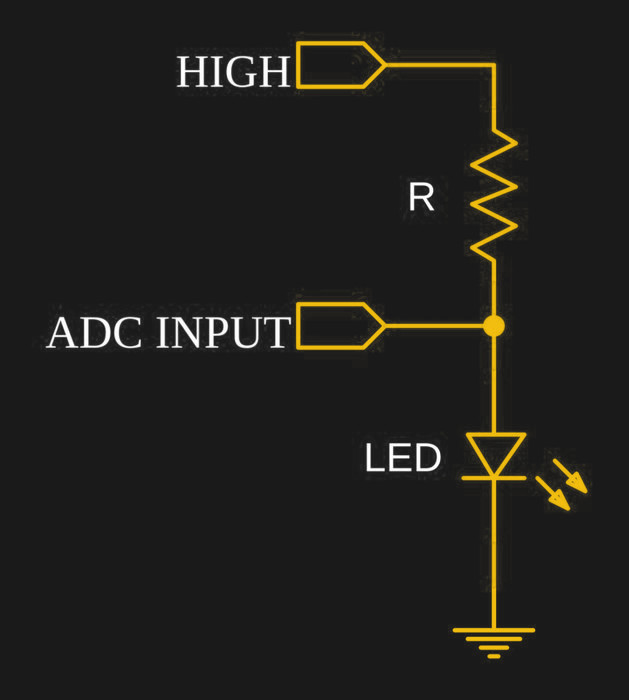
The first step is a thermistor, a conceptually simple device: resistance varies with temperature (seriously, how much more simple can a sensor get?). You can measure them by tapping the center of a voltage divider the same way you’d measure any other resistance, but [Edward] had discarded this idea because the naive approach combined with his Arduino’s 10 bit ADC yielded resolution too poor to be worthwhile for his needs. But by using the right analog reference voltage and adjusting the voltage divider he could get a 20x improvement in resolution, down to 0.05°C in the relevant temperature range. This and more is the subject of the first post.

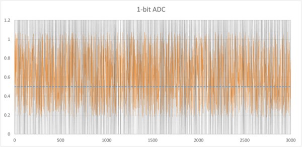
What comes next? Oversampling. Apparently fueled by a project featured on Hackaday back in 2015 [Edward] embarked on a journey to applying it to his thermistor problem. To quote [Edward] directly, to get “n extra bits of resolution, you need to read the ADC four to the power of n times”. Three bits gives about an order of magnitude better resolution. This effectively lets you resolve signals smaller than a single sample but only if there is some jitter in the signal you’re measuring. Reading the same analog line with no perturbation gives no benefit. The rest of the post deals with the process of artificially perturbing the signal, which turns out to be significantly complex, but the result is roughly 16 bit accuracy from a 10 bit ADC!

What’s the upside? High quality sensor readings from a few passives and a cheap Arduino. If that’s your jam check out this excellent series when designing your next sensing project!

An LED You Can Blow Out, With No Added Sensor

We’d seen it done with buttons, switches, gestures, capacitive touch, and IR remote, but never like this. [electron_plumber] made an LED that can be blown out like a candle, and amazingly it requires no added sensors. The project uses an Arduino to demonstrate turning a tiny LED on and off in response to being blown on, and the only components are the LED and a resistor.

[electron_plumber] used an 0402 LED and thin wires to maximize the temperature responses.
How is this done? [electron_plumber] uses an interesting property of diodes (which are the “D” in LED) to use the LED itself as a temperature sensor. A diode’s voltage drop depends on two things: the current that is being driven through the diode, and the temperature. If the current is held constant, then the forward voltage drop changes reliably in response to temperature. Turning the LED on warms it up and blowing on it cools it off, causing measurable changes in the voltage drop across the device. The change isn’t much — only a handful of millivolts — but the effect is consistent and can be measured. This is a principle [Elliot Williams] recently covered in depth: using diodes as temperature sensors.

It’s a clever demo with a two important details to make it work. The first is the LED itself; [electron_plumber] uses a tiny 0402 LED that is mounted on two wires in order to maximize the temperature change caused by blowing on it. The second is the method for detecting changes of only a few millivolts more reliably. By oversampling the Arduino’s ADC, an effectively higher resolution is obtained without adding any hardware or altering the voltage reference. Instead of reading the ADC once, the code reads the ADC 256 times and sums the readings. By working with the larger number, cumulative changes that would not register reliably on a single read can be captured and acted upon. More details are available from [electron_plumber]’s GitHub repository for LEDs as Sensors.

Embedded below is a video that is as wonderful as it is brief. It demonstrates the project in action, takes a “show, don’t tell” approach, and is no longer than it needs to be.

Continue reading “An LED You Can Blow Out, With No Added Sensor”

When Adding Noise Helps

It’s a counterintuitive result that you might need to add noise to an input signal to get the full benefits from oversampling in analog to digital conversion. [Paul Allen] steps us through a simple demonstration (dead link, try Internet Archive) of why this works on his blog. If you’re curious about oversampling, it’s a good read.

Oversampling helps to reduce quantization noise, which is the sampling equivalent of rounding error. In [Paul’s] one-bit ADC example, the two available output values are zero volts and one volt. Any analog signal between these two values is rounded off to either zero or one, and the resulting difference is the quantization error.

In oversampling, instead of taking the bare minimum number of samples you need you take extra samples and average them together. But as [Paul] demonstrates, this only works if you’ve got enough noise in the system already. If you don’t, you can actually make your output more accurate by adding noise on the input. That’s the counterintuitive bit.

We like the way he’s reduced the example to the absolute minimum. Instead of demonstrating how 16x oversampling can add two bits of resolution to your 10-bit ADC, it’s a lot clearer with the one-bit example.

[Paul’s] demo is great because it makes a strange idea obvious. But it got us just far enough to ask ourselves how much noise is required in the system for oversampling to help in reducing quantization noise. And just how much oversampling is necessary to improve the result by a given number of bits? (The answers are: at least one bit’s worth of noise and 22B, respectively, but we’d love to see this covered intuitively.) We’re waiting for the next installment, or maybe you can try your luck in the comment section.

Vintage DACs And A Raspberry Pi

DAC

Before the days of iPod docks in every conceivable piece of audio equipment, most devices were actually built very well. Most shelf top equipment usually came with well designed circuits using quality components, and late 90s CD players were no exception. [Mariosis] heard of some very nice DACs found in some of these units and decided to take one out for a spin. He’s using a Raspberry Pi to play audio with the DAC found in a late 90s Kenwood CD player.

After fortune favored a CD player with a dead drive on [Mariosis]’ workbench, he dug up the service manual and found some interesting chips – a PCM56 DAC, a little bit of logic, and an SM5807 oversampling chip that does all the conversion for the DAC.

This oversampling chip uses an I2S – not I2C – bus to carry the data from the CD to the DAC. There is, of course, an I2S driver for the Raspi, but the first attempts at playing audio didn’t result in anything. It turned out there was a problem with what the oversampler expected – the ‘standard’ I2S signal delays the data one tick behind the LRCLK signal.

There are two ways to fix this problem: programming a kernel driver, or building some custom logic to fix the problem. Obviously breaking out some flip-flops and NOR gates was the cooler option, giving [Mariosis] a great sounding stereo with a vintage DAC.