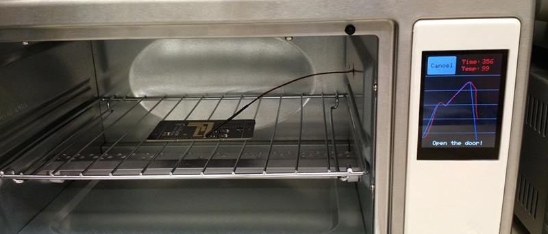
[Will] had a few reasons for turning a toaster oven into a reflow oven – he needed a project for an ECE lab, the lab’s current reflow oven was terrible, and the man is trying to keep [Will] down by not allowing toaster ovens in dorm rooms. What was born out of necessity actually turned into a great project – a reflow oven with touchscreen controls.
The toaster oven used for this build is a model [Will] picked up at Sears. It’s actually pretty unique, advertised as a ‘digital toaster’. This isn’t marketing speak – there’s actually a thermistor in there, and the stock toaster is closed loop. After disassembling the toaster and getting rid of the guts, [Will] whipped up a PCB for a Teensy 3.1 and the Adafruit capacative touch shield.
With the Teensy and touch screen, [Will] came up with an interface that looks ten times better than anything you would find on a Chinese auction site. It’s a great build, and since it’s kept in the electronics lab, will certainly see a lot of use.


Better than the original.
Great design aesthetic and execution!
This is a great hack and I really respect the effort put into it (looking nice, touch screen) and the video is good quality too!
That’s a nice looking build, but I would worry about how hot the PCB is going to get and the particularly the impact on the cold junction compensation. My toaster oven easily got to 60C in the side section. Maybe this one is a bit better than mine.
I measured it, it’s actually well isolated. When the toaster is at peak temp the side section is about 35C.
MAX6675 has internal cold junction compensation within its operating range ( -20°C to +85°C). You want to keep the thermal couple chip (MAX6675) close to the thermal couple connector in the layout.
Amazing work there. This is definitely one to add to your resume as employers like seeing things you have done.
Only suggestion I have for v1.5 or the next revision is to put your 5v signal traces further away from your 120vac traces. My company does UL listed boards for our controllers and 120v trace separation is 42mil. We often sat our DRC in EAGLE to 47 mils for safety. Just a few trace tweaks and this board would be much better isolated, especially with those high currents. Impressive work and I think I might be working with a coworker to build one for us.
Huh, I had no idea this isolation was quite so important. Thanks! I guess all I really wanted to avoid was having any traces under the AC lines,but that makes sense.
FYI: PCB isolation distance http://www.smpspowersupply.com/ipc2221pcbclearance.html
What? No Convection blower? It will have hot spots for sure…
This is probably the nicest toaster oven reflow refit I’ve seen.
If you like this one, you will probably like this other one as well:
http://hackaday.com/2014/10/11/toaster-oven-reflow-controllers/
Thanks for the link! might need to build one of these soon just for the heck of it :)
What was the total cost?
Around $180
Very nice looking build and the documentation seems to all be in order as well. Seriously thinking about building one of these.
On the PCB though there are a few ‘gotchas’ that have mostly already been pointed out.
The Groundfill around the mains traces is way too close, also add isolation slots.
The thermocouple IC should be pushed closer to the junction block and groundfill removed from the area surrounding it (but keep the fill that links between the connector and IC) as well as possibly add isolation gaps The idea is to have it very thermally conductive from the screw terminal to the IC, but not cause a thermal gradient across the PCB, it will just make it a less accurate. Think of what happens if you touch an ice cube at one end of a piece of metal then a torch on the other, a large varying gradient occurs, now slice the metal in half and put a piece of fiberglass between the gap, same idea, the hot side gets uniformly hot and the cold side gets uniformly cold, the gradient is mostly erased and the CJC chip does it’s job better.
Very nice. Check out the Zallus.com controller. The Kickstarter rewards have been sent out. Its great would be easy to install the same way this one is.
Whenever i try to do anything with the code for this project i get “Error : Redefinition/Previous Definition of Class TS_Point” and “Error : Redefinition/Previous Definition of Class Adafruit_FT6206” Errors
Hi Grant,
where to contact you?
Hello Grant,
add at topof Adaftruit_FT6206.h
// Very top of the file
#ifndef ADAFRUIT_FT6206_H
#define ADAFRUIT_FT6206_H
.
.
and at the bottom
#endif
I can compile the Firmware but the screen remains blank ??
There is a mistake in Eagle sch and PCB is missing one wire…
Where is this mistake? I ordered the pcb…
Wow, this is the nicest DIY reflow oven I’ve seen, and it just so happens I’ve got a pile of Teensy boards on the bench.
But… has anyone got this to work? The code compiles after adding the #ifndef #define fix to the Adaftruit_FT6206.h, as suggested by marjanmencinger, and then screen goes blank.
Then there’s the chicken-and-egg problem that the controller board uses some pretty challenging SMD parts (0603 resistors? Ouch, not what I had in mind for a first-try had hand-soldering). While the board would be a touch bulkier, having either primarily through-hole or perhaps-larger-than-necessary-but-hand-soldering-friendly components would make this much more accessible to folks just starting to explore DIY SMD fabrication. That plus the UL-inspired improvements to the mains routing would be a nice next rev.
Did anybody successfully compile this project recently?
I get errors during compile and also once code gets to arduino screen works but, and all screen buttons work except “reflow”
Check out screenshots here – http://imgur.com/a/5x85j
When we downloaded the sch files there was no schematic. It was a blank piece of paper with grid. We are using Altium Please post the schematic or email to us.
We have purchased most of the parts.
Do you have a layout pictures of both sides of the board.
Thank you
Ross
We downloaded Eagle Viewer and have schematics
Need to verify if you use external power supply
We get compile errors- do you have a newer version of code?
Try to use old Arduino Compiler !!
Code works ! Upgraded – https://www.youtube.com/watch?v=lxk77F82L7Y