Populating a board with tiny SMT parts can be really tricky, and we’ll take all the help we can get. If you’re in the same boat, [vpapanik] has two devices you should check out.
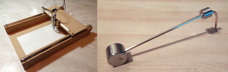
First up is the manual pick-and-place machine. Wait, what? A manual pick-and-place? It’s essentially an un-driven 2-axis machine with a suction tip and USB inspection microscope on the stage. The picker apparatus is the “standard” needle-plus-aquarium-pump design, and the rails are made from angle aluminum and skateboard bearings.
Yeah, yeah, yeah. It’s not a robot. But sometimes the right jig or tool makes all the difference between a manual procedure being fiddly and being graceful. And we couldn’t help but laugh at the part in the video where he demonstrates the “machine” moving in a circular pattern.
The SMD Beak is just a weight for holding down SMT parts as you hand-solder them in place, but it’s beautiful. The round base means it’ll always push downwards, and the weight up top provides the force. The thin point will work even for 0402 parts. It’s a great design, doing exactly what’s needed and nothing more. (We use one arm of a helping hand precariously perched on its side, which now looks really crappy in comparison.)
All in all, two great ideas for making your work with SMT parts more precise and comfortable.
Thanks [RasmusB] for the tip!


I like the idea of the manual pick’n’place but can’t say that it has many advantages (in its current form) over a microscope and tweezers as the motion is still direct to your own hand (albeit with somewhere to rest your arm). I think it would be better if either there was more dampening of the motion (to reduce any natural ‘twitch’) or a reducer for the hand motion (so you have to move your own hand, say, twice as far, for a given tool motion – think: pantograph with a scaling factor)
Commercial manuals often come with a foot switch to toggle ‘breaks’ on x, y or both axis. on the z axis there might be a finger trigger and springs.
I’d like to see all axis lock up when close, and then some sort of fine jog controls.
Do these commercial units just lock the axis with the brake or do they rather add some friction? If they add friction, how is that done?
Not entirely sure.. but guessing its just a solenoid with rubber pad, adding friction.
Could be electric or air depending on design.
If I were to build one, I’d go for air.. electric solenoids get big at that level of spring pressure.
The extra fiction and inertia might help to damp the motion. I tended to overshoot while working under a microscope initially. It took me a while to match my motion with the magnification. Now if only there are better cheap USB microscopes that does lag like hell.
Could use some lights under that gantry or built it with a transparent material.
that’s brilliant…
it seems to achieve smooth movement and to remove hand shaking enough to provide a very professional work
Exactly my thoughts as well. I started using wrist rests in the through-hole days to get a better joint and not tire out too quickly. Some people may shun these types of devices, but I doubt they have a very active bench. Someone was ridiculed in the comments of another article for saying he used a bamboo skewer to count pins. I use a pointer like everyone else and have doubts about anyone who claims they can visually count pins on small packages. Same goes for people who say this nice piece of work isn’t necessary. I’m building this for sure.
The same project has been featured here 2 years ago:
http://hackaday.com/2012/11/24/an-inexpensive-manual-pick-and-place-machine/
Quantity not quality, get it up and check it later, what’s wrong with HaD today. I did like the tiny part holder idea though, has other applications than just SMD, very elegant design.
And yet, it is new to some people. What difference does it really make? Do people really have so much free time that they go and search every article on Hackaday trying to find out if it was posted years ago?
Who cares?
Why don’t you people use that free time to actually build something new for Hackaday to post about instead of wasting it fricking complaining all the time!
Thank you, you’ve given me an idea for my next project.. an irony detector.
I do need to replace the canooter bearing in mine. It exploded once and I never repaired it.
I like the idea of the beak and the nice clean design. However, for most SMT parts you’re likely to be using hot air and solder paste and want the surface tension of the paste to centre the component for you. Is this for use with a soldering iron, or for those tricky components that tend to tombstone?
Could be useful to line up BGA/fine pitched/leadless parts before dropping them because you can isolate the X/Y/rotation motions.
As is the camera only see one side. It might make more sense to have a option for angled tips and to get a much better over head view of a large part for centering.
I was talking about the “beak” part holder rather than the manual pick and place.
My guess it’s for a soldering iron. Using paste doesn’t make a lot of sense when you’re soldering the components one by one.
When I hand solder SMT, I just put some solder on one pad, then stick the component in, and then do the other pad. That’s probably quicker than having to set up the beak
Actually I find that way very easy : apply a small amount of paste using a toothpick, use the beak to hold down the component, and touch the pad with the iron for one second. Works great every time.
Mhh… neat. I wonder if it would be possible to bend the vacum suction tube at a 90° angle 5mm above the tip so he could position the camera centered above the component. The angle is kinda weird (for me at least).
Fran Blanche (of Apollo DSKY fame) made a similar SMD hold-down tool out of a silicone-tipped dental probe, here:
http://www.frantone.com/designwritings/design_writings5.html#hold
I’d rather like to make one using slate for the weighty base, partly because it’s dense but non-conductive, and partly because it’s an unusual material.
How unusual a material seems is mostly due to how close you are to it. There are a lot of slate quarries around my hometown so slate is a fairly common material for all sorts of things: decorative objects, chopping boards, signs, flooring, counter tops. People even used to use six of them and some lead to make water tanks, although I guess that was before lead was known to be so bad for one’s health.
I wish I had a photo of an old conveyor we use to have on our commercial Pick and Place line. It was essentially the same thing, but without the foot switch. It might have looked a little better when we first bought it, but also cost us several thousands of dollars…
For the home hobbyist, this is a nice quick and dirty arm rest jig though.
I had bought a lot of the parts and materials to make the first one but never followed through. We had a bunch of boards that needed building, but it was too late to have it machine populated. It was also too late to build any of these machines.
This is something (the “beak”) that probably most electronics folks have made at one time or another ;-) I made a rather overkill version using a ball-bearing doohickey from a printer and an optical post –
http://imajeenyus.com/electronics/20080628_pcb_soldering_arm/index.shtml
I’m not entirely sure why I went down that route, with the little holders for MSOP8 packages. I _think_ it was related to working on PowerPAD devices, which have a heatsink on the bottom. I aligned the chip on the board, then could flip the arm up, solder a heatsink to the bottom, then flip it back down again in exactly the same position and solder it to the board. Actually……no, that’s not it either. I think I put a blob of solder on the backside of the chip, then lowered it, then heated the groundplane of the board until it melted the blob of solder and the chip settled, then soldered the legs.
Subsequently I made copper-foil heatsinks for the chip, which avoided the need for all that:
http://imajeenyus.com/electronics/20080713_powerpad_heatsink/index.shtml
End of digression….