
It’s simple, it’s elegant, and it works really really well. The PicoRico team built a telemetry system for a downhill bike. Off the top of your head how would you do this? Well, telemetry is easy… just add an IMU board and you’re golden. They went beyond that and have plans to go much further. In fact, the IMU was an afterthought. The gem of this build is a sensor that may go by several names: string encoder, draw wire sensor, stringpot, etc. But two things are for sure, they planned well for their hackathon build and they executed on that plan. This landed them as first-runners-up for the top award at the 2015 Disrupt Hackathon in New York, and the winners of the top Hackaday award at the event.
 [Chris], [Marek], and [Dorian] wanted to log all the telemetry data from [Chris’] downhill bike. One of the biggest challenges is to measure the force absorbed by the suspension on the front fork. The three had seen a few attempts at this before. Those used a retractable wire like what holds keys to a custodian’s belt, mated with a potentiometer to measure the change. This is where the term stringpot comes from. The problem is that your resolution and sensitivity aren’t very reliable with this setup.
That is a sensor problem, not a mechanical problem so they kept the retractable reel and replaced the pot with a much more reliable part. In its place an AMT203 absolute position sensor provides an epic level of sensing. According to the datasheet (PDF) this SPI device senses 12 bits of rotation data, can be zeroed over the SPI bus, and is accurate to 0.2 degrees. Unfortunately we didn’t get a good up-close shot of the installation but it is shown in the video. The encoder and retractor mount above the shocks, with the string stretching down to the skewer. When the shocks actuate, the string extends and retracts, turning the absolute encoder. Combine this with the IMU (and two other IMUs they plan to add) and you’ve got a mountain of data to plot and analyze. The videos after the break show a demo of the string encoder and an interview with the team.
 They came to play
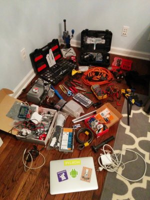
It’s worth noting that the PicoRico team were in this to win it. They packed heavy for the 20-hour hackathon. Here’s a picture of all the gear they brought along with them to the event… in addition to the bike itself.
We see a solder station, Dremel (with drill press), impact driver, tap and die set, extension cords, boxes full of electronics, and more. This type of planning breaks down barriers often faced at hardware hackathons. You can download a software library; you can’t download a tool or building material that nobody has with them. This is the same lesson we learned from [Kenji Larsen] who, as part of his mentoring at the event, brought a mobile fabrication facility in a roller bag.
If you start getting into hackathons, and we hope you will, keep this in mind. Brainstorm as much as you can leading up to the event, and bring your trusted gear along for the ride.


In my opinion, the telemetry of the bike suspension is far to be near real with this hack. When the suspensión is compressed and decompressed quickly the read is a small amount of compression but when is decompressed and compressed the read is near reality. This hack can read decompressions but no compressions.
Not sure I understand what you are saying? We are installing the string encoder with its string 80% extended so it is always trying to retract via the internal badge holder spring as the suspension compresses. Also when the suspension rebounds it is extending the string again so it is measuring both compression and rebound fairly well. The encoder has surprisingly little friction so it moves smoothly.
you are right! Dani. The time response when the thread is release (on compressions) is a lot slow that real movement!
Just install two of them in opposite directions: one with the encoder in the sliding part, one with the encoder on the “fixed” part of the shock absorber.
Cabling it up reliably might not be simple though…
Yes. with two of them you do the trick!
Why not use one of those linear hall effect sensors? You can seal them up to make them waterproof and just put them on the fork. Embedding a magnet might be hard, though.. mainly like this project, however they did it. http://pcm52.com/
We looked into hall effect sensors but we wanted a design that could be quickly attached and detached with the minimal amount of adjustment and calibration required. We should be able to achieve the same with a custom hall effect setup but I think it would have taken us a lot longer to get there. Putting research time aside and thinking pure manufacture of the sensor we had the string encoder built and getting data in under 5 hours for the first run. Applying lessons learned from this we should be able to create new sensors in an hour or less. Attaching it and removing it from the bike currently takes less than a minute and there are some improvements we can still make there.
Why did they not just grab parts from motorcycle racing?
You simply tap off the fork’s fluid fill at the top with a pressure sensor and you get instant data from the forks.
Well, some forks are air filled and no liquid in them beside the grease.
So drill a hole, fit a port, add a sensor.
Refill with air.
Oh, by product = adjustable shocks.
bad name, here in Chile picorico means tasty dick
George Lopez (i.e., the stand-up comedian) said that “chilito” is a slang for the same part of the male anatomy, particularly an undersized one. It was also the menu name for a chili and cheese burrito at Taco Bell.
Use a LVDT to measure the displacement. It is within the reach of a determined hacker to build the transformer and signal conditioning.
http://en.wikipedia.org/wiki/Linear_variable_differential_transformer
Yeah commercial LVDTs are the defacto standard. http://www.vitalmtb.com/photos/features/PIT-BITS-2013-Andorra-World-Cup,5645/Remi-Thirions-Commencal-with-Data-Acquisition-System-on-BOS-Suspension-at-Andorra,59915/sspomer,2 Aside from cost reasons we are trying to shrink down the footprint of the sensor and make it easier to add/remove. We might build a LVDT similar to the steps in the article you mention to do side by side accuracy comparisons to be sure we are not making too many compromises while simplifying/shrinking things.
Yet again, I thought I had hit upon a solution to a problem I’ve been wrestling with, but no.
I need to be able to control and monitor the position of a rotating shaft over a range of 400 degrees or so. At face value, this encoder would work, but I need to be able to know the position from a cold start, which this can’t do.
The best I can think of is a servo+ multiturn potentiometer, but they’re quite expensive and have a minimum of three turns, which means I’m wasting resolution. By similar token, comments in a recent post about continuous rotation servos mentioned 4-turn boat winch servos. In principle that would work, but they’re too large; space constraints mean a 9g servo is about the largest I can accommodate.
A long-term lurker becomes a first-time poster in the hope the Hackaday masses can make a suggestion.
The encoder is absolute so it does know its position and you can actually use their api to define reference points at particular positions as needed. This was one of the big reasons we went with the slightly more expensive absolute model versus their incremental model.
Yeah, but from what I could see in the data sheet, it’s absolute within one rotation. Yes, it outputs a pulse when it completes a full revolution, but consider what happens if you disconnect it for a moment, turn it one (or more) revolutions and reconnect; how would the software ever know? That’s what I need: absolute position over a >360 degree range.
Of course, if you think I’ve /still/ misunderstood, I’d love to be corrected!
Sorry did not realize you needed to account for >360 rotation while the encoder is powered down. Seems like a mechanical counter could be used with computer vision to read the count and then when the encoder is powered back on you could read the finer degree within that counts rotation.
The powered down case was more by way of example; in real life, I’m not going to be doing multiple turns, nor doing so with the power off.
I need to know where I am within about 400 degrees of rotation, primarily to avoid driving past that range. Mechanical endstops are not viable, but exceeding the range of motion would cause damage.
In a perfect world, I could use a 360 degree encoder like the one you’ve used and simply keep track of the index counts to extend the range. The problem I have is if I have an uncontrolled reset for some reason, then there is no (reliable) way to determine where I am within the full range of motion. I could be at 10 degrees or 370 degrees. It would be bad news for my application to make the wrong guess!
Would it be possible to split off the encoder on a reduction transmission so one original shaft rotation will keep you within the bounds of 360 degrees for the encoder shaft?
I’m trying to avoid any kind of gearing, really. Space and complexity constraints make it a bit of a no go.
The “known position from a cold start” part can be easily solved with the Gray code optical encoder. I have once designed a quick response suspension position sensor for a racecar, using a sliding bar with 7-bit (128 valid positions) Gray code represented in black and white areas, passing next to a line of 7 reflective IR sensors. The rest was just a microcontroller with a lookup table.
The Gray code’s purpose is to minimize the error while one of the sensors is at the threshold point: In straight binary, the transition from 63 to 64 for example would be easy to interpret as all sorts of nonsense. The Gray code’s elegance is that just one bit changes between adjacent values.
The sensor was surprisingly effective, unfortunately it has not been used in the end.
The encoder can be made with a disk instead of a bar, preserving the concept – but whoa, 400 degrees. How about an elastic spiral-shaped encoder sliding through the sensor?
The spiral-shaped encoder could totally work. I salute you!
How would this account for the multiple rotations beyond 360 degrees while the encoder circuit is off?
Thinking about it, corkscrew would be a better term, rather than spiral. It would allow as many rotations as there were rotations in the corkscrew encoder. It would not allow continuous rotation (as your encoder does) but I don’t need that.
Good luck then! Glad to be of any help. Indeed, corkscrew was the term I was looking for, but English is not my native language. Fortunately You have grasped the idea! I’d love to see it work!