[NurdRage], YouTube’s most famous chemist with a pitch-shifted voice, is back with one of our favorite pastimes: buying cheap equipment and tools, reading poorly translated manuals, and figuring out how to do something with no instructions at all.
[NurdRage] recently picked up a magnetic stirrer and hotplate. It’s been working great so far, but it lacks a thermometer probe. [NurdRage] thought he was getting one with the hotplate when he ordered it, he just never received one. Contacting the seller didn’t elicit a response, and reading the terribly translated manual didn’t even reveal who the manufacturer was. Figuring this was a knock-off, a bit more research revealed this hotplate was a copy of a SCILOGEX hotplate. The SCILOGEX temperature probe would cost $161 USD. That’s not cool.
The temperature probe was listed in the manual as a PT1000 sensor; a platinum-based RTD with a resistance of 1000Ω at 0°C. If this assumption was correct, the pinout for the temperature probe connector can be determined by sticking a 1kΩ resistor in the connector. When the hotplate reads 0ºC, that’s the wires the temperature probe connects to.
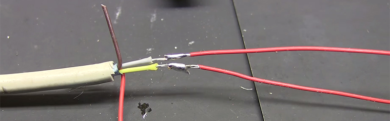
With the proper pin connectors found, [NurdRage] picked up a PT1000 on eBay for a few dollars, grabbed a DIN-5 connector from a 20 year old keyboard, and connected everything together. The sensor was encased in a pipette, and the bundle of wires snaked down piece of vinyl tube.
For $20 in parts, [NurdRage] managed to avoid paying $161 for the real thing. It works just as good as the stock, commercial unit, and it makes for a great video. Check that out below.
Thanks [CyberDjay] for the tip.


“a platinum-based thermocouple” you might want to correct that, a thermocouple is an RTD using the change in resistivity with temperature of a material, unlike thermocouples which use the Seebeck effect
A thermocouple is NOT a RTD. An RTD is an RTD.
Thermocouples work using this crazy thing called the Seebeck effect. Basically two dissimilar metals joined at a junction, when heated, will natually have some potential.
This voltage is then read with a very sensitive amplifier and AD pair.
Generally this also requires compensation with a “cold reference” temperature sensor, and for long runs of wire, compensation at the termination point.
Interestingly, RTD sensors, which are resistive, do away with the need for cold junction compensation or special wiring concerns, and also have other desirable properties over thermocouples.
Each have their place and are not the same thing.
Sorry, should probably triple check my post when correcting someone. The first “thermocouple” was supposed to be “PT1000”, thanks for setting that right.
A PT1000 is not a thermocouple. It’s an RTD.
Thank you, because the true heroes of hack-a-day are not those who spend the hundreds of hours innovating and sharing their cool projects with the world, but rather the ones who hang out in the comments section, correcting everybody.
You’re welcome. Because the youngsters that read these blogs don’t always know better and get their heads filled with wrong information that they pass on to their peers.
And before you know it Hackaday.io is full of ridiculous things like perpetual motion machines, electronic sex toys, and absurd ideas that never actually turn into a real project.
https://hackaday.io/project/5075-van-de-graaff-generator-free-energy-brainstorm
https://hackaday.io/project/4660-freeenergy-for-the-world
https://hackaday.io/project/3835-computer-vision-dildos
https://hackaday.io/project/3846-heartbeat-sensor-tutorial
https://hackaday.io/project/3492-digivibe
https://hackaday.io/Comingle
https://hackaday.io/hacker/37146-99guspuppet
https://hackaday.io/project/5126-weeed
From time to time I do come across projects here whose description could use some careful technical editing. I find that I must restrain myself from getting to pedantic. I usually only comment on technical inaccuracies in the most egregious cases. There are ways to diplomatically comment that will lead a reader in the right direction but that can be tricky balancing your comments between diplomacy and beating someone over the head, metaphorically, when “contributing” corrections.
Also as an engineer the most difficult documentation to write is one describing your project in enough technical detail so that those without the background in the particular circuitry will understand it. Now throw managers (often non-technical) into the mix and the writing is even more difficult.
and I really hate people that ask for stupid analogy for something technical.
But what is an RTD?
https://en.wikipedia.org/wiki/Resistance_thermometer
Plugging stuff into random holes.. Story of my life.
The heating regulation will overshoot with this kind of build: thick glass, isolating air and the big pt1000 itself will give it a very slow response time.
maybe pouring in some molten lead, or smash an aquarium thermometer and steal the little lead balls?
A sand bath would typically be used for this type of heating, but I have never seen a stirrer / sand bath.
The bare thin film pt sensor can easily fit inside a ptfe tube, heat the end until it goes clear and then squish between pliers to close the end off, _much_ more responsive than NurdRage’s lazy build.
I expect the Scilogex original with its 5 pin connector to use 4-wire measurements. He is lucky the knock off doesn’t. Otherwise he would never have found two pins that worked probing like that.
Most RTDs don’t bother with the full 4-wire setup. You get almost the same accuracy with just three wires, and even then it’s important only for long lines with a lower-resistance PT100 probe. A PT1000 can get by with just two wires with leads this short.
(real numbers from our real hardware: a 4-wire configuration is given to be accurate. A PT100 RTD on 3 meters of 28 ga 2-wire cable will show an error of a few degrees. With a 3-wire configuration it’s a few tenths of a degree. A PT1000 will be just a few tenths of a degree off with just two wires and, if they’re short, it will be in the ballpark of a tenth of a degree.)
One of the main reason RTDs (100 ohm or 1000ohm) use 4-wire measurements is to null out connector resistance. You can null out the resistance of the wires (and unless you buy a calibrated RTD you will need to do this as a part of the calibration, and if you paid for a calibrated one you probably care well down into the hundredths of a degree), but you cannot account for the varying resistance of a connector. A normal DIN connector is rated with a contact resistance of ~.05 ohms, which is nearly half a degree on a 100ohm device. Moving to a 1000ohm device mostly mitigates the issue for low-precision work, but for precision work you still need a 3 or 4-wire setup to be guaranteed better than a tenth of a degree accuracy
For the applications that a stirrer/hotplate gets used for being within a degree or three of the correct temperature is fine–reproducibility is more important. The main use will be heating a beaker (half) full of some solution whilst stirring it–there will be temperature gradients from top to bottom and from inside to out even with the stirring action. The effects of contact resistance etc. are minimal.
A class-A rtd is only +/-0.15’C at 0’C
The hotplate doesn’t read 0°C but 1°C
Look at the resistor. Gold band = 5% tolerance. That’s why the reading is slightly off.
That poor vintage keyboard :(
RTD can be interfaced also using a very low cost RTD to 4-20 mA transmitter. http://s.click.aliexpress.com/e/QNVNnYf .It’s loop powered, so the current in the power source is “modulated” by the transmitter and can be readed with a precision resistor and ADC pin