Rotary indexer’s are standard issue in most machine shops. These allow you to hold or chuck a work piece, and then a graduated handle lets you to rotate the workpiece. Useful when you want to drill or tap axial or radial features. A rack and pinion drive ensures that the workpiece does not move under machining load. Quite often, these indexers also have a manual lock to take care of gear backlash and play. Automating them is not too difficult either. You could use just a stepper motor (open loop) or servo+encoder (closed loop) to drive the turntable.
[smashedagainst] needed to drill six radial holes on a part. And he had to do it on 500 pieces for a total of 3000 holes. That was just for the first initial run, with more drilling likely in the future. The part in question was small and light weight. So instead of using a heavy duty, industrial grade unit, he built an all-electric rotary indexing jig using a stepper motor and an Arduino, giving him a sort of rotary 4th axis. His idea was to directly use the stepper motor to rotate the workpiece without any gearing, but he needed to build his own rig to do so.
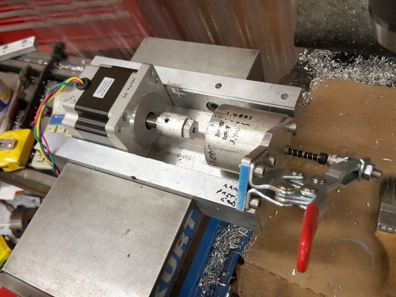
His initial prototype used an Arduino Uno, which he swapped for a Pro Mini in the final version to save some space. The Arduino was connected to a Rugged Circuits motor driver. This was the only driver, out of the several that he tried that managed to hold the stepper motor with enough torque to prevent the workpiece from moving while drilling. The number of holes to be drilled is hard-coded in the Arduino, so all he needed was a single button. Each press of the button advanced the stepper motor through 60 degrees, giving him six, equally spaced holes. He used a NEMA-34 stepper motor, and that meant a beefy power supply. He scavenged a power supply from an old laser printer which conveniently had 24V DC as well as 5V outputs.
The next step was to work on the mechanical assembly. He machined an arbor that is attached to the shaft of the stepper motor. The face of the arbor is hexagonal and the workpiece wedges/locates over this. The motor assembly is fixed on one end of a base plate. The other end of the base plate has a clamping mechanism activated by a toggle clamp. It is also able to rotate (much like a live centre on a lathe). The workpiece is mated to the arbor, and the toggle clamp then locks the piece in place. During initial trials, some of the assembly fasteners worked loose, and there was some amount of chatter from the drill bit. He fixed these issues, and found it performed best when he set the spindle speed at 2400 rpm. Once he got it working, he was able to finish a hundred parts in under 2 hours. Drilling six holes in quick succession causes the part to get quite hot, so he first used some pressurised air cooling. Later, he switched to a spray can based multi purpose penetrant lubricant. Watch his video of the indexing jig in action below.


Oh, neat!
It took me months to convince the main engineer where I work, to buy some of those rapid clamps for making tooling. XD
I’m not sure a stepper motor can turn exactly 60 degrees. If they’re 400 steps/revolution:
360/60=6 400 steps/6=66.666667
So, to turn 60 degrees, the motor has to take 66.66667 steps, and it can’t. If you use 800steps/revoution, it’s 133.33333 steps for 60 degrees.
Depending on the precision he needs, that could be not enough.
Any idea if he found any solution to this issue?
Micro stepping with the stepper driver?
1/16 or 1/32 are used a lot in 3d printing maybe that gets him close enough for the designed tolerances.
checked the source code. he’s doing single stepping.
Micro stepping will not give nice even steps, some will be bigger, some smaller…
Think about this: If he wants exactly 60 degrees, how many full or partial turns will advance far enough to give an exact multiple of 60 with single stepping? The new position doesn’t actually need to be the next adjacent hole, as long as all positions can be reached.
But all positions cannot be reached, not with 200 step/rev nor with 400 step/rev steppers. It would need 1:3 gearing to reach exactly 60 degrees.
Am I missing something? the stepper seems to be 1:1 to the workpiece and it has no brake mechanism apart from the nema34 holding torque, which is far too low for holding index securely.
I made a 4th axis from a 1600oz/inch stepper ran at 80v with 2:1 ratio and it didnt have enough holding torque for securely holding the workpiece still while operations happened. I would recommend anyone gets as high as drive ratio as they can early on in the design as the problem is not top speed (unless your planning on using the axis as a extra rotary spindle too) but holding torque.
My mk1 :-
http://gallery.pipandphil.com/d/38794-1/4th_axis.jpg
Ive since modified mine to drop the drive ratio to 8:1 and added a em brake using a mini moto brake disk. Still not happy though as now turning it into a diy trunnion table axis so need even more holding torque…
Just, been there, woudln’t implement this like the op. Flame away.
“Am I missing something?”
Yes.
The motor is used just to rotate the piece. Once indexed, the toggle clamp locks it in place.
The toggle clamp only keeps the piece from falling off the adapter on the stepper shaft.
Had he been going for higher precision he could have drilled tapered holes into a flange** on the adapter that would line up with a hole in a fixed part and then use a solenoid actuated pin to lock the adapter in position, which would also make up for the mismatch between the desired 60 degree turn and the amount of turn reachable with the stepper (not evenly divisible by 6) The pin would also mean a smaller stepper might be used, but since the stepper shaft is also resisting the drilling loads it is probably a wash.
**Basically an index plate, but one could use a gear and have the pin come in radially
Thanks dave, thats how I read it.
I wanted the toggle clamp to be a manual brake and watched the video of it in operation, but it was just there as a workpiece holding method afaik.
Anool, or you could just add a relay to control a actuator to push a mechanical brake into actuation for clamping force like I did later on.
The whole point behind my post isnt to bash op, its to pass on learning from doing it myself.
The Arduino was connected to a Rugged Circuits motor driver. This was the only driver, out of the several that he tried that managed to hold the stepper motor with enough torque to prevent the workpiece from moving while drilling.
It sort of helps if you actually read *every word* before responding.
I found my spindle held when radially drilling, then I went to drill offset to the centre and found it moving under load and was disappointed in my own design. I ran the numbers and it had 7lb/ft of holding torque. Emprical experience on how much 7lb/ft felt like said it was never going to be enough to be secure.
Just trying to pass that don’t do as I did and expect stepper at 2:1 to have enough holding torque on. Its as much don’t do as I did as do as the op did.
I noticed in the build log that one part got damaged due to operator error and wondered if changing the setup to trigger when the quill handle is all the way up would be a good idea. This would mean no separate action from the operator would be needed and there would be no chance to trigger the system with the tool still in the cut.
Of course everything is obvious -after- seeing it in use.
And making an index plate with six notches and having the toggle lock onto that was obviously too hard.
(And more accurate as noted above)
When all you have is an Arduino…
I guess he didn’t have one. But they aren’t too expensive, and even the Chinese dividing head sets are pretty cheap these days, and the precision is adequate for most work.
https://www.youtube.com/watch?v=-we6ORrJgUI
He could have made one easily enough. Didn’t even need to do that, just index on the flat of the nut.
A bit pointless automating the axis when you need to clamp and drill by hand anyway.
I agree.
I disagree. He had to make 500 of these things – doing that with a manual rotary axis would have taken forever. It’s a nice hack for what I assume (not having rtfa) is a one-off job.
I was a bit surprised that he was drilling by hand – not sure how consistent the depths would be but maybe that doesn’t matter for the application.
His lock/release mechanism is well executed, All in all a very good hack.
Maybe next he can motorize a dividing head.
…and the key part of the summary is “…once he got it working…”.
People never factor in setup time & cost, there’s nothing like spending a day to save a few minutes.
But eh, if he’s happy.
Doug: the vertical mill has a work stop on the quill, so depth is consistent. Yeah, would do it exactly like this again. I refuse to set up every single hole. Clamping and reclamping 3000 times for this first run wasn’t an option for me and I didn’t want to pay an employee to do it. The idea was born from the though of something that turned or clamped to the 6 sides of a hex bolt. But those are not consistent enough (nor are they centered).