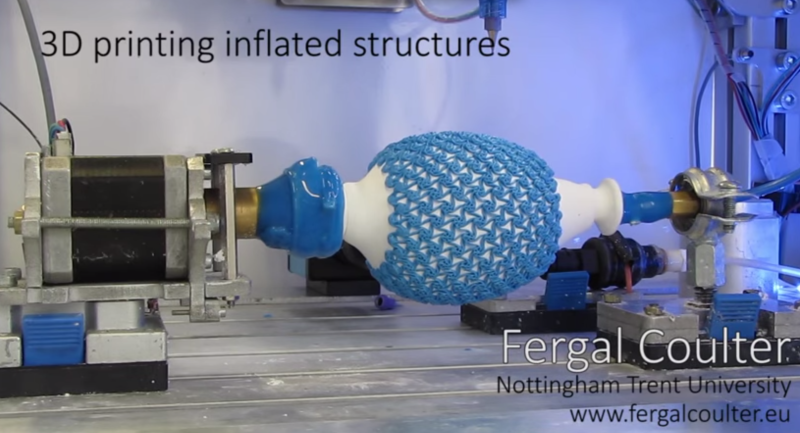
Just when you think you’ve seen it all… [Fergal Coulter] over on the RepRap forums just came up with a method of 3D printing on inflatable structures — wait what?
The process uses a custom 3D printer with a paste extrusion head, and a 4th axis — with a pneumatic air supply. Using a spray deposition method, a silicone tube is formed, and then each layer is cured using a infrared light, which is also built into the system. Once the silicone is thick enough, it is then pressurized to inflate through the air-permeable mandrel. A laser then scans the shape of the inflated silicone to allow the computer to generate tool paths for the surface. Then you hit print. Simple right?
We’re not even sure how to begin explaining how he came up with this. Basically, this method of 3D printing allows for the manufacture of some very unique flexible components, perhaps the most interesting application is “Dielectric Elastomer Artificial Muscles” which is a really advanced form of pneumatic artificial muscles (which you can make from hardware store parts too). It would also make building a soft robot much easier than casting the silicone muscles by hand like we saw last week.
It’s a fascinating new direction for 3D printing and we’re excited to see the technology continue to advance. There’s more information available on [Fergal’s] main website.
[Thanks for the tip Matt!]


DAM’s have nothing to do with PAM’s except they both contract. This is nothing more than art, albeit very cool art but the process could be applied in a different geometry with different materials to make high strength AMA. He’s on the right track in my opinion and its great to see people working on AMA’s.
Very pleasing to watch and he has an excellent website.
TLAs (or As in general) are probably not appropriate in an article of this sort, with the intended-audience, without explanation.
Sorry DAM or DE is Dielectric Elastomer Artificial Muscle using things like Carbon Nanotube Aerogels to electrostatically contract, there are also converse piezoelectric effect muscles as well that use piezoelectric polymers like PVDF. A PAM is a pnuematic artificial muscle the most common being Mckibbon Muscles that use air pressure to expand a sleeve causing a contraction. And obviously there are the soft expansion muscles the soft brobots use. There are also shape memory alloys like nitinol and polyamides and aramids that demonstrate properties useful for making AMA artificial muscle actuators.
Awesome, thank you for that! “And thorough”
Hi Johnny, you are right in pointing out these structures are not Pneumatic artificial muscles, but my video shows part of a process for making Dielectric Elastomer Actuators (DEA). I would argue there’s a little more reason to it than just for arts sake!
What i’m making is a form of “Dielectric Elastomer Minimum Energy Structure” (DEMES), These are DEA that have been mechanically stretched and then adhered to a support frame.
There’s a nice video showing a DEMES in action here :
https://www.youtube.com/watch?v=nZm36KMVvy8
In this case I use inflation to impart mechanical strain in the sprayed membranes, then extrude a hard silicone (Shore ~80A) around the outside to act as a support frame. I’ve been printing auxetic (collapsable) structures which can deflate evenly with the balloon.
When the internal pressure has been reduced to the point that it no longer plays any part in stretching the balloon, and any strain that is maintained is a product of the (printed) support frame alone, you could say they’re minimum energy structures.
To be a proper actuating ‘artificial muscle’, the membranes must be ‘intersplilced’ with stretchable electrodes – effectively making a stretchable capacitor. I haven’t implemented these steps yet, as I decided it was outside the scope of my PhD (which i handed in today, incidentally!) – Though you might notice in the video, before spraying, the mandrel is coated in graphite. This isn’t the ideal electrode material, but would work. I simply used it to delineate layers so i could measure the evenness of the spray deposition over the curved surface.
Adding a large electrostatic charge difference between the silicon spraying nozzle and the target would make that part of the process a little less messy.
That’s a great idea! – particularly if spraying onto an irregular shape. Somewhere between electro-spinning and powder coating.
It is a very messy (and wasteful) process spraying silicone – as the poor fume-cupboard in my university can attest!
Yes, they are a thing, http://www.airspray-gun.co.uk/buy-spray-gun,electrostatic-spray-guns,0.html
fabulous – thank you for that!…
Goodness – they nearly cost more each than the entire budget I had for the project above! :)
at 68-85kV, they use a much higher potential difference than I expected (I was considering using a little 4kV DC transformer to see how it would go.)
Do you have experience – or could point me in the direction of any papers – that describe a (high viscosity) droplets reaction to various levels of HVDC. In truth, i found very little published on spraying elastomers during my research, Apart from some using the fabulous (but cruelly expensive!) Optomec Aerosol Jet…..
Thanks!
Fergal
Looks like a super egg-bot printer, that can make its own eggs.
What’s the advantage of building a pneumatic artificial muscle this way instead of using “hardware store parts”? It seems like conventional manufacturing techniques have the advantage of being cheaper, faster, easier, and more robust, while the 3D printer method has the advantage of being pretty cool and (most importantly) giving your project lots of blog cred.
Progress.
Once this advances, you could do some really interesting thing’s you wouldn’t be ably to do normally.
Indeed! The interest that people are showing is really delightful! :)
As i mentioned above though – this process isn’t for making pneumatic (McKibben) muscles – though they were an inspiration.
Instead its about making Dielectric Elastomer Actuators which will expand in area when exposed to a high voltage (2-3kV) !! They’re extremely energy efficient as actuators go – they maintain their charge (which can be re-couped), and as they’re capacitors there is no (significant) current flow.
Hypothetically these could eventually end up being implantable in the body as prosthetics such as artificial sphincters (not the most glamorous class of prosthetics, but the relatively simple action would be easiest to achieve, and would be of great benefit to some people)
Unfortunately there are no studies on the long term effects of the electro-magnetic radiation from these actuators so they may never be used in that way…
@zach, it’s the bespoke aspect (bespokability? customizability? something) of it.
What if you need very specific muscles for a very specific prosthetic?
What if they need to be made on-site?
It’s a machine that can create this sort of custom product using a modular resource. That’s the important aspect of 3D printing – mass customization, digitized to order.
Can anyone point me toward more info on the mechanics of the printed material and the patterns printed? He says it’s hard silicone on his site. Does the curing process or the pattern make it contract from its cured state?
The muscle contracts to a relaxed state as silicone is an elastomer. The silicone will return as it was sprayed and cured.
On the mechanics of a McKibbon muscle and the function of the 3d printed plastic look here https://en.wikipedia.org/wiki/Pneumatic_artificial_muscles
This would be a more appropriate wiki to look :
https://en.wikipedia.org/wiki/Dielectric_elastomers
The patterns printed are mostly ‘auxetic’ – that being a geometry which will collapse / contract evenly in all directions when subjected to an applied force.
https://en.wikipedia.org/wiki/Auxetics
More specifically, the geometries are ‘Hexachiral Structures’. There is a good paper written by Dr Jonathan Rossiter : https://www.researchgate.net/publication/260419589_Shape_memory_polymer_hexachiral_auxetic_structures_with_tunable_stiffness
which discusses the pattern in depth.
I chose these structures to print as I felt they would allow the ‘balloon’ to deflate evenly – holding some of the tension but not all. The contraction you see is as a result of removing the compressed air (the video is greatly speeded up at that section!).
The material i extruded is silicone – the hardest i could get was Shore 73A, but with mineral additives i increased that to over 80A.
As i mentioned above, they’re not true artificial muscles (yet), as i’ve only made the passive components (so far!), and not the electrodes which are required.
Does any one here have experience adding the 4th axis to a 3D printer? I’d imagine it would be like the 4th (rotational) axis on a CNC machine, but I am having trouble visualizing how layers would work here. Or should I think of the layer as a 3D wrapped structure?
Think of the layer as a tool path,This is more of a 3.5d printer as the axis he prints on is just a curved surface. As the curved surface rotates the tool is understood to be moving by the machine. Thus the layer or tool path is simply applied to a 3d surface as opposed to the plane of a regular FDM machine.
Ahh… Now I see. Thanks.
There are some tricks to having a fourth axis in additive manufacturing, over subtractive CNCs – one of the trickier parts is keeping a constant material thickness extruding over the surface. This is due to the substrate (the balloon in this case) increasing and decreasing in circumference – and so as it is turned, the surface linear velocity changes. To compensate for this, the print-head movement and substrate rotation speed is decreased in proportion to the increasing surface velocity
I found it was best to keep the geometry described in Polar co-ordinates, and only convert them to Cartesian (XYZ & Ө) at the end.
The geometry is very much a wrapped structure when it’s generated, but i unwrap it, in quite a similar manner to a how a projection of the world can be flattened out on a map.
https://en.wikipedia.org/wiki/Map_projection#Pseudocylindrical
Each layer that is added can be calculated by offsetting the surface (in essence calculating what the balloon would be like if it were inflated evenly by 0.4mm for each layer.
It’s a tricky process to explain fully!
In essence what JohnnyRico says here is correct, though i’m not sure what an extra half ‘dimension’ would look like! This is a true four axis, 3D printer, which can make ‘4D printed’ objects (that being objects that change form and geometry after the print process)
So how would one go about taking a single layer, and wrapping it onto a 3D structure (in software)? I can see how one would print around the circumference of a cylinder for example, by simply rotating the 4th axis instead of moving the Y axis (or X axis depending on your perspective).