Most 3D printing projects start with a 3D model of some kind. Slicing programs transform the model into gcode. The gcode file contains the commands that actually drive your printer. There are different ways to slice a model and sometimes you want to use more than one on a single model. I’ve been working on a way to make that easier.
When you slice a 3D printing model, you can select different attributes for the resulting gcode file. For example, you might set the slicer to produce different infill density, temperatures, or print speeds. These settings can have a big impact on your printing results. For example, a piece that needs high strength might require a denser infill than some trinket or key chain. You might want an artistic piece to have a finer layer height than some internal part for some gadget no one will ever see.
One Size Fits All?
The problem is that for most open source slicers, these settings will apply to the entire model. Cura has some plugins that can change settings at different Z heights, and Slic3r can vary layer height, but in the general case, what you set for the slicer will apply to the entire model. Of course, a gcode file is nothing more than a text file, so if you are industrious, you can manually merge two or more files into one.
A manual merge is a pain, which is why I wrote gblend. It can stitch together gcode files to get various effects. The program takes multiple gcode files in as inputs and can combine them in different ways. The most useful feature allows you to get a certain number of layers from each source file and combine them into a single print. Measurements are in millimeters, so you don’t have to worry about layer numbers. The entire process is much easier than anything else I’ve come across.
When to Use Multiple Slicing
For a common solid object, you don’t really want 100% infill. It takes too long to print, and it also can cause problems with warping. Practically, a 20% or 30% infill is strong enough for most purposes. However, there is a common case where you don’t want any infill: if you are making a vase or cup.
 In the case of a vase or a cup, you are really only printing the walls of the object and you want the inside to be completely empty. Most slicers have a “vase” or “spiral” mode that will do this automatically. When set, the resulting gcode will trace the outline of the object with a single plastic filament. There won’t be any layers, just a coil of plastic building the entire shape.
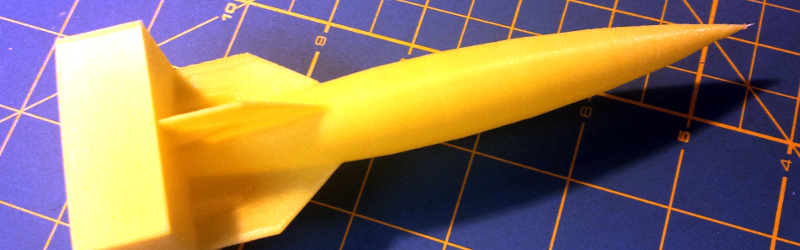
The rocket in the picture is a model from Thingiverse that is meant to be printed using a spiral or vase slice. However, I imported the model into OpenSCAD and added a 20mm high base (this would make a good award-style trophy if you added a name plate).
Ideally, you’d like the base to be solid (well, as I mentioned, 20% or 30% infill). Printing the rocket solid, though, is a waste of plastic and changes the item’s appearance since it will have layers instead of a single filament.
Solid vs Spiral Slicing


When you slice the entire model as a solid object, it becomes a series of layers. To the left you can see ten layers from the middle of the base at the bottom of the rocket. Each layer has diagonal lines in one direction and the layers alternate. Taken together, you get this crisscross pattern (although you can select other patterns in the slicer software). The tube of the rocket, unfortunately, looks the same. To the right you can see ten layers from somewhere along the tube.
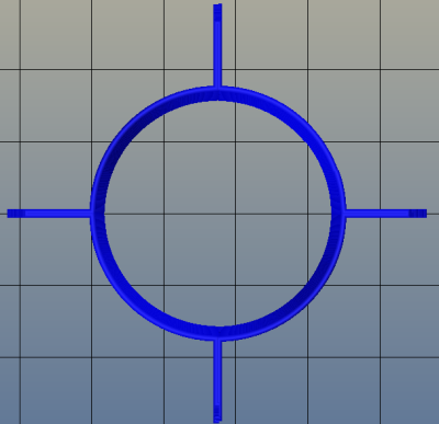 Remember, both of those pictures are only ten layers. When you slice the model as a spiral, each layer contains just one spot, and the layer distance becomes very small. Ten layers for the spiral sliced model would just be a small line segment made up of ten dots. Here’s about 1,000 spiral layers near the rocket’s fins:
Notice the tube is hollow and the 1,000 layers makes just a few concentric rings. Once the files are blended, you’d expect to see the base as a cross hatched, layered object and the rocket body as a hollow tube all in one file.
Blending the Files
The key is to slice the same model twice. One time you slice the entire thing solid. The second time you slice it all with the spiral slice setting active. Knowing the base is 20mm high, you can use gblend to select portions of each file. You can see a video walk through of the process below.
The gblend software is a command line tool. To use it, you do need to make a small modification to your slicer’s configuration. A slicer will have somewhere to set your start and end gcode. This is usually code that will start the printer’s extruder, set temperatures, and send calibration data to the printer. At the end of the start gcode, you need to add a comment:
; %%%GBLEND_START
At the beginning of the end code, you need to set a similar comment:
; %%%GBLEND_END
Because these are comments, it is perfectly fine to leave them in all the time. You also need to make a copy of your desired start and end codes and put them in separate files for use later. The gblend software will ignore everything before the start comment and after the end comment, so you will need to have the start and end codes added in to the new blended file.
Once this is set up, just slice the model as you usually would, saving each time to a different file name. In my case, I wound up with four files:
- start.gcode (you can use this file with any model)
- end.gcode (used with any model)
- rocketstat-solid.gcode (the model with a 20% infill)
- rocketstat-spiral.gcode (the model with a spiral slice)
The command line tool should work under Linux or Windows (you might find it easier to use Cygwin if you use Windows and there are prebuilt binaries on Github). Here’s the command line I used:
gblend = start.gcode [ rocketstat-solid.gcode 20.0 rocketstat-spiral.gcode ] = end.gcode >rocketstat.gcode
The project’s home page explains all the options, but for this example, all you need to know is that the equal sign copies a file to the output; the open bracket gets the start of a file; and the 20.0 stops the first file at the 20mm mark and starts the next file. The close bracket tells gblend to take the rocketstat-spiral.gcode file all the way to the end.
Beyond the Basic
The resulting rocketstat.gcode file will print and have a solid base and a hollow rocket. Of course, you could get lots of effects using this technique: Different layer heights, fill patterns, cooling settings, speeds–anything you can instruct the slicer to change. There’s no reason you can’t have multiple segments, too. For example, I could have switched back to the solid model for the tip of the rocket, or selected a third gcode file if I wanted to.
While it isn’t rocket science (despite the printed model), it does automate an otherwise tedious task. Give it a try!


When I first started reading, I was under the impression it actually ‘blended’ two gcode files together…
From the sounds of it, it does less blending, and more automated splitting and file joining.
Find the desired Z-Height in file one and delete everything after. Find the desired Z-Height in file two and delete everything before.
copy start+file1+file2+end output
If it wasn’t for the splitting portion, that one liner could do it in windows.
Congrats for the efforts though. Now can you take it further than that? (ie, what if you printed the rocket on it’s side… this can only split and join files based on layers)
Yes, I’ve done it by hand before. But even for a simple case like this it is error prone (at least, it is for me). With the right use of options, you can do other things too like edit out pieces. Of course, you can do everything by hand if you want. Particularly when I work with students, though, it gets tedious very quickly.
Actually, I thought the same thing about the copy (using cat) when I started. But the problem is you duplicate the start and stop codes. And, as you say, you don’t get the first file to stop and the second file to start at the same place. You’d wind up with two rockets, one atop the other and strange start and stop codes in the middle.
I agree, there’s more to do with gblend but that’s the great thing about it being on Github. Anyone can fork it and contribute!
Well.. when working with students or anyone else for that matter, anything to automate the task (if robust enough) will help the outcome… The wrong copy/paste can cause quite a mess…
I do the same thing with G-Code files for a 3-Axis CNC at my shop.
The programs they have paid for are… limited to only using one tool at a time. So I’ve shown them that they can output 2 or more files, and merge them with a ‘magical’ program. (It essentially removes the last 4-5 lines in a file, the appends the next file onto the first and so on.)
I’m betting with a little extra effort, you could make it merge the same layer from two files together ;)
ie. Left hand side of the model is solid, right side is hollow. Tool path each region by itself and merge the files. It would be like merging two decks of cards together.
Good Job by the way.
Neat! Though to add a quibble, I’d put hollow cylindrical areas in the base made so that some coins can, post print, be squeezed in. For added weight.
Honestly, I created this model just to have a simple example of using gblend, but that’s a great idea. You can put pauses in Gcode, so you could make a hollow cavity, throw some washers in (I’m too cheap to put in coins) and then restart the printer to print over it trapping the washers in. I’ve done that with nuts before and it works very well. I bet fishing weights would work too.
To insert pieces inside prints i usually get to the layer i want, get the extruder out of the way, wait 5 sec and resume work. I’m looking to add an option to the slicer configuration.GBlend could be added to host programs:-)
Are you sure that pennies are more expensive by weight than washers?
Very good idea Al, I could have used this 2 days ago, I needed 3 top layers on a shorter section of my part and no top layers at the finish, with 200 micron layers I just added 600 microns to my model and stopped the print instead. I’ll have to try this out soon.
I wanted to write that one could use the .AMF format but stumbled over the .3MF format… why ist there nothing on Hackaday about that???
3MF is Microsoft and 6 or 7 other player’s answer to AMF which is XML’s answer to STL. As far as I know, though, you still have to slice the model and the printer still takes gcode. Are there printers that take AMF or 3MF directly? That would seem odd to me unless the printer itself is doing the slicing since the files don’t know about tool speed, flow rates, and layers as far as I can tell.
At some stage you have to slice the model, i don’t think there is a way around that. with more capable processors in the printers one day the printer itself could do the slicing.
What I wanted to point out: With AMF you can have more than one parts with different properties in one file and therefore it should be possible to use different slicer options for different parts.
Personally, I’m still waiting for someone to create ‘Postscript 3D’, where each layer is defined by PS commands.
Can’t you just have each postscript ‘page’ become a layer?
Another useful addition would be a way to quickly load a file that is failing while printing. and select the range using m measurements, or some feature?) to allow a restart after manual clean of top of print…
Simplify 3D already has the ability to do this much easier and quicker. It’s not free though, it’ll cost you $150 for the software.
Forgive me if I’m missing something obvious but doesn’t slic3r already do this?
http://slic3r.org/blog/modifier-meshes
Yes it does if you can build up a modifier volume in a CAD program and export it as an STL. Cura has a plug in too that will work, too. But this works with all slicers and even if you want to mix Gcode from different models (e.g., take a base off of one and the top from another). If I’m not mistaken, In previous versions of Slic3r, I think, you could only modify the layer height, although I think that’s no longer true. It is still more challenging (although also more powerful) to be able to specify the modifier volume.
Is there a way to do an open cell infill so that resin can be poured into a print to make it solid?
how about not closing the bottom of your printed object?
Very cool, I have had this issue and Gblend seems like a good answer. Can it insert a pause and head retract to allow for filament color change?
I have thought about doing something automatically. You could probably do it (untested) by having a pause.gcode file and inserting = pause.gcode in the command line where you wanted it to go. So something like:
gblend = start.gcode [ part1.gcode 100.0 = pause.gcode [100.0 part2.gcode ] = end.gcode
If that works, report back! Well… if it doesn’t work, report that back too (file a problem on github).
Why not a graphic based editor that imports g-code directly and lets you work on it by layer or layer groups? Putting some information about your printer including nozzle diameter and filament diameter could result in knowing heights, etc. and allow for some pretty powerful editing.
Since g-code is the last thing before making it into the printer, we really need tools to work directly with the g-code. This is certainly a start. I have Simplify3D and it is the closest I have seen so far to this, but it is still not as intuitive as selecting individual layers visually.
I wrote an X3G parser a while back, that could crop and merge files and modulate the temperature per layer for making gradients with wood filament, it also does visualization in OpenGL.
If there is an interest in visually cropping/merging files I’d be motivated to further develop it.
What other file formats are common for 3D Printers, I can’t imagine anyone using ASCII G-Code ..
inserting pauses with waitforkeypress and the head moved out of the way also seem simple to implement .. so if there’s any interest ..
That sounds great! Some tools to do this rather than manually would be very helpful.
Slic3r has been able to do that for a long time, see http://slic3r.org/blog/modifier-meshes
It was the first slicing software to introduce that feature set. It also reads AMF files which define several object parts, and it also reads AMF metadata specifying the part-specific settings such as infill density etc. so that you could even set those overrides in the CAD software before exporting.
The G-code stitching approach doesn’t always work: for example it only works if your parts include entire layers and are stacked. But you can’t define different settings for multiple objects in the same print, or within a single layer.
I’ll soon implement some handy commands for defining the modifiers inside the Slic3r 3D interface, instead of importing them from a CAD. It’s easy, just a matter of creating a cube and positioning it in the space. :)
Agreed the AMF metadata is great. If you only have STL files to start with this is an option. It would be good if Slic3r would have the ability to do it without creating a new 3D file. There is a Cura plugin that just lets you pick layer heights, but I haven’t used it.
Interesting. I know you can configure multiple sets of print parameters on an object-by-object or Z-height basis in Simplify3D but I don’t think even that lets you switch between regular and spiral printing in the same part. I’ve found the feature quite useful for upping the layer heights and reducing fill where I could for faster printing, and reducing layer height for detail or adding more infill for strength where needed.