
We love shop made CNC mills, so when [joekutz] tipped us off about the desktop sized CNC he just completed, we had to take a look. Each axis slides around on ball bearing drawer slides, and the machine itself is constructed with MDF and aluminum. And the results it produces are fantastic.
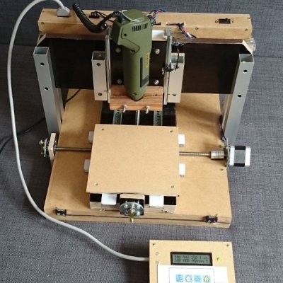 The machine’s work area weighs in at 160*160mm with a height of 25mm. Its the table is moved around with a pair of NEMA17 motors and M8 stainless steel threaded rods. Motor control is done with a pair of Arduino’s but they also do double duty with one processing G-code while the other handles the keypad and LCD interface.
The business end is a Proxxon rotary tool whizzing up to 2000RPM, and while [joekutz] hasn’t tried it on soft metals like brass or aluminum, he has successfully cut and engraved wood, plastics and copper clad PCB material.
Be sure to join us after the break for some YouTube videos. [joe] has posted three of a planned five-part-series which aren’t linked to in the project page shown above. to see this machine in action and get a rundown how it all works


The other problem with drawers slides is that the ball bearings slip. They are not necessarily center to both halves of the slide.
If you don’t move the slide all the way to the end every time, the bearings will start to creep to one end and the slide starts to catch. Then it has to be dragged until the bearings are re-centered, which also wears down the soft metal slides and eventually the whole thing becomes sloppy.
Hmm actually an interesting point, I did not notice it (yet). My sliders are “closed” on one side each, so theoretically, when I run a homing/max loop, the ball cages should be centered again. When my loop starts in the wrong direction (need to check ;) ) then some balls may actually fall out .. would be a pain then to get them in again.
It may require considerable force to reset the bearings since you have so many balls just dragging. The contact patch of each is small, so it’s essentially like pulling a 16 tooth rake along the metal surfaces. I would be surprised if it didn’t just jam at some point.
If the dragging is difficult, the misalignment wouldn’t have happened in the first place.
The misalignment happens when the slide is unevenly loaded and travelling, which wedges the individual balls towards one or the other end and the rolling action allows them to rattle along without sticking.
Then when the entire ball cage has moved off-center, it catches on the end and all the balls jam at the same time.
This pretty much happens with drawer slides in actual drawers. After some time, the drawer doesn’t open fully anymore, and you have to tug it the extra inch that the ball cage has shifted.
I sort of agree with rewolff. My ball cages did not seem to have moved since I built the machine and had it milling stuff for 5 hours in total. I guess it helps that the stress is always above the ball cages, see second video. I will check from time to time whether they have moved. However, the wear of the rails actually might become a problem in the future, although nothing is visible right now.
Considering the cost difference between the slides and linear bearings you could afford to replace them on a preventive maintenance schedule and still be money ahead.
Why not add strip with holes or comb-shaped piece of thin plastic to minimize ball’s clustering?
The sliders actually come with such strips. This can be seen in the third video where I show a slider disassembled somewhere. Without the strips, the balls would in fact go anywhere.
Nice work! A CNC router is on my todo list…
Nice build!
But Kevin:
“…Hardware *Store Parts…”
Also: *Arduinos (no apostrophe, see http://theoatmeal.com/comics/apostrophe)
xo
I am currently building a CNC, Got a few parts already but I was thinking of using slide rails. On either side of my lead screw I was going to use these
Stainless Steel Rods
http://www.ebay.co.uk/itm/A2-STAINLESS-STEEL-Round-Bar-Steel-Rod-Metal-MILLING-WELDING-METALWORKING-/181308547444?pt=LH_DefaultDomain_3&var=&hash=item2a36d4e174
Bearing slides
http://www.ebay.co.uk/itm/4x-SC8UU-SCS8UU-Linear-Motion-Ball-Bearing-Slide-Bushing-for-Machine-Tools-/281397093270?pt=LH_DefaultDomain_3&hash=item418492e396
Rod Supports
http://www.ebay.co.uk/itm/2-16x-8mm-SK8-Motor-Chrome-Linear-Rail-Shaft-Guide-Support-Bracket-Bearing-Step-/400885520731?pt=LH_DefaultDomain_3&var=&hash=item5d56a3995b
I was wondering if anyone could see any problems with using this kind of setup? Would I be better to go with drawer rails? If there are problems with what I have picked do you think it is still workable?
Also I think your build is pretty cool, I will be following your progress on youtube and see what tips and tricks I can pick up.
The slider parts you choosed look like the typical choice for CNC mills, I don’t see a problem with that. This setup may live longer than my drawer slides ;)
Hey thanks for replying, Yeah I never thought to do it with drawer slides. I like that you have done it different, I will try and document my build too. Iamjust buying parts at the moment piece by piece trying to get all the components together to spread the cost over a few months. I am following you on youtube looking forward to seeing how you get on with the build.
I just saw that your rod-diameter is 8mm, wich is not a lot. How much travel distance do you need? When the sliders are too long (my gut feeling says more than 30cm) they might bend under pressure like a spring.
I bought 8mm already waiting on it being delivered, I only bought 30cm so I was going to use for z axis. The reason I decided Z axis first was incase it was no good then it is cheaper to bin it and buy something else. What diameter do you recommend for any other axis?
Hmm.. there’s also these rails with a “foot” along the whole length, and linear bearings that have a gap at one side. They might be the better choice: http://www.ebay.co.uk/itm/12mm-linear-slide-guide-shaft-SBR12-250mm-2-rail-4-SBR12UU-bearing-block-CNC-set-/151215056777?pt=LH_DefaultDomain_3&hash=item23351ea789
Besides that, my gut feeling says.. 15mm diameter should be good even for rails longer than 30cm.
It’s weird to me that he didn’t just use a RAMPS setup with Arduino — RAMPS is a common Arduino shield that can control up to 5 stepper motors (with a common A4988 or DRV8825 stepper controllers, you can get 5 of them for about $10 to $15 now, and you can easily configure microsteps up to 16x or 32x with them…), and you also get 3 high current outputs if necessary, and 3 analog inputs, and 6 end-stop inputs.
Plus, you can optionally connect an keypad / LCD / Buzzer / SDCard slot to it, and there’s a ton of firmwares for it (mostly tailored to 3D printers, but they’re not so smart that you couldn’t just use one for CNC milling instead, and some of the firmwares *are* for CNC milling)…
You can buy a full RAMPS 1.4 electronics kit (including an Arduino Mega 2560, and motor controllers) on amazon for around $50 – $60 USD.
I have chosen my setup because I had already half of the parts to begin with, so I ended up paying not more than what you mentioned. Also: I wanted to write my own software, not use a off-the-shelf one.
I am actually bringing back to life a mill in my local hackerspace right now .. with exactly the setup you described. Which firmware would you recommend?