How long can you keep an Arduino circuit running on three AA batteries? With careful design, [educ8s] built a temperature sensor that lasts well over a year on a single charge of three 2250 mAH rechargeable cells (or, at least, should last that long).
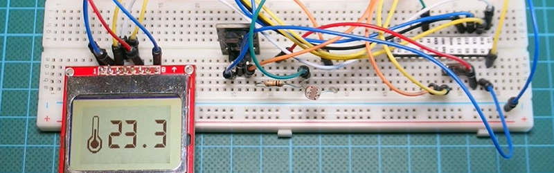
Like most long-life designs, this temperature sensor spends most of its time sleeping. The design uses a DS18B20 temperature sensor and a Nokia 5110 LCD display. It also uses a photoresistor to shut off the LCD display in the dark for further power savings.
During sleep, the device only draws 260 microamps with the display on and 70 microamps with the display off. Every two minutes, the processor wakes up and reads the temperature, drawing about 12 milliamps for a very short time.
Along with the code, [educ8s] has a spreadsheet that computes the battery life based on the different measured parameters and the battery vendor’s claimed self discharge rate.
Of course, with a bigger battery pack, you could get even more service from a charge. If you need a refresher on battery selection, we covered that not long ago. Or you can check out a ridiculously complete battery comparison site if you want to improve your battery selection.


Interesting idea. But I’m not thrilled with his website. Incidentally first posting costs something……
So how does the $10 alarm clock/calendar on my desk with temperature and humidity sensor get a year out of a single LR44 (150 mAh, 1.5V)?
A much slower, and *probably* more purpose built uC.
I’m more surprised at how my watch (Casio ABX-20) with its mechanics can run for several years on a single SR920W (30-40mAh, 1.55V). I have this watch for more than 20 years now and I had to change the battery only a handful of times.
“A handful of times”?
I suppose it depends on the size of the hand, and the size of the times. Assuming an average time is 2cm^3, I’d say I can fit about 25 times in my hand.
I thought it depends on the number of digits (fingers + thumb) on a hand.
Nope, that’s how many times you can count on one hand.
Nice usage of sleep mode for ATMega, battery life of one year for 0.5° accuracy thermometer seems very good. But I guess using alkaline batteries would be better. The reason is 328 micro works fine with as low as 1.8V, when three AA pack hits 1.8 it means that single cell is at about 0.6V, that is point of no return for NiMH batteries.
Not to mention the much higher self-discharge rate of NiMH compared to alkaline.
70 μA is a huge amount of current for a sleeping microcontroller. In a well-designed system, sleep currents under 1μA should be quite possible. I haven’t watched the whole video, but here are some general strategies, in no particular order:
* Turn off all unnecessary clocks, and run necessary clocks as slow as possible while sleeping. If you can get by with just waking up on an external interrupt, all clocks can be off while asleep. If you need to wake up periodically, use a low-power RC oscillator (like the one for the watchdog timer on the mega328p). When powered on, there is a tradeoff: a faster clock requires more power, but means that the work can be finished and the chip can go back to sleep sooner.
* Use the power reduction registers to turn off all unused peripherals all the time, and used peripherals when they are not needed, especially if there isn’t a long reinitialization time when powering them back on.
* Turn on the pull-up resistors on all unused GPIO pins. If they are left floating, the inputs might flip back and forth randomly, needlessly consuming power.
* Turn off brownout detection if you can. It consumes a significant amount of power. If erratic behavior (and possible memory corruption) is intolerable when your batteries are dying, some microcontrollers have a sampled BOD mode that uses much less power. You can also implement this yourself in software with an ADC and bandgap (or other stable reference), checking your system voltage only periodically (like once a day) and shutting down before it gets too low.
* Voltage dividers, like the one for the photocell in this project, consume power—current flows from power to ground through the two series resistors. Size the resistors as large as practically possible, and bias the voltage divider with a GPIO pin that can be turned off when the sensor is not needed rather than just tying it to Vcc.
* Voltage regulators can have significant quiescent current draw. If at all possible, power the circuit directly from batteries without a regulator. A pair of AAs, or a CR2032 coin cell are both good 3V supplies, and most microcontrollers are very happy with this. If regulators must be used, specifically choose ones with very low quiescent draw.
* Electrolytic capacitors can also have high leakage currents—avoid them in power supplies or choose low-leakage versions.
* Rechargeable batteries are generally a poor choice for long-life low power applications. Self-discharge rates can often be higher than the load of the circuit itself! Non-rechargeable lithium batteries are a good in these applications.
* Generally, less power is consumed at lower voltages, so running as low as is practical can be advantageous. However, often sensors and other devices will have higher voltage requirements than the MCU, and the complexity (and additional power draw) of translating between multiple voltages often isn’t worth it, nor is regulating down from whatever battery voltages are available (unless it’s a significant drop and you’re using good switching regulators). Depending on your battery chemistry, running at the minimum voltage might also mean that you can only run your battery down so far before you start browning out.
Thanks for this, learned quite a bit!
Also ensure, if possible, that any external pull-up or pull-down resistors work along the state of the signal that it spends the most time in. If the GPIO has to fight against the pull, significant (in this context) current is drawn through the resistor for a long time. E.g. a 100k pull-up on a signal that is active-low will draw 30uA at 3V as long as the signal is asserted. If at all possible, design the system so this signal get a pull-down instead, then it will only draw 30uA when NOT asserted.
And of course, choose pull resistors as large as practically possible. 100k draws 1/10th of a 10k. Be aware of issues that may follow with too high values, e.g. larger values lead to slower charge/discharge of a capacitive load, etc. Like everything, it’s a balance.
Also, as bdm said, bias low-power rails from a GPIO pin if possible, it allows you to power-off external components of parts of your circuit completely. Be aware of possible switching noise etc on the “pin supply” though.
Alternatively, consider using an external power-switch transistor to the same effect if the circuit is too high power to be sourced from a pin. However, when switching parts of your board off, be aware of any reverse-feeding of the powered-off components. I.e. an external IC might be unexpectedly reverse-powered e.g. through the I/O protection diodes, if some signal from a still-powered MCU is driven high.
Also consider effects like power-on recovery/reboot times and in-rush currents etc when switching things back on.
Not to forget: ensure no IOs are floating. Either make them outputs or ensure they are connected to ground or a power rail. If you are paranoid: make them inputs and pull them up.
Instead of a transistor I prefer a (second) LDO with low quiescent current draq like the TPS 783xx with enable input. So you can power-off all external components not needed.
I do a lot of low power applications at work (with MSP, never had to handle Atmel for low power) and with the “usual” tricks you and bdm mentioned >1uA applications are no problem
So here we go, throw your AA batteries out of the desing an go with a cr2302 cell, easy as 123 :D
yeah, it really depends on the current. If you are well below the pin’s drive strength, no need for extra components.
Both the AVRs and the MSPs will be able to achieve kind of the same low power, but the user has to know what he is doing. Don’t remember the numbers for the megas, but for the xmega family power down with RTC, WDT and BOD is under 1uA.
Neat. I was just reading about ways to reduce the power consumption of the Arduino for long term sensing applications.-
https://hwstartup.wordpress.com/2013/03/11/how-to-run-an-arduino-on-a-9v-battery-for-weeks-or-months/
And let’s not forget Nate’s “Aventures in Low Power Land” where he shows a range of tricks that can put an Arduino to sleep on just 1uA:
https://www.sparkfun.com/tutorials/309
I’ve made identical version and the atmega328 draws only 3uA during sleep. however the display still draws 200-300uA all the time.. what a rain on a parade :)
Could you use a tiny solid state relay (or FET) to cut power to the display while the ATMega is sleeping?
Or use I/O to power the LCD directly and skip the MOSFET. When it is over a few mA, then it is time to think about MOSFET as the I/O might has more I*R drops.
Good idea!
He forget to derate the batteries mAh for voltage drop at end of charge life. See http://www.eneloop.eu/index.php?eID=tx_nawsecuredl&u=0&g=0&t=1437889810&hash=950e877305129db5a3d8e6e08134a0203242d77f&file=/fileadmin/web_data/Data-Sheets/BK-3HCC.pdf
A nice conservative estimate is take 15% off the stated mAh to ensure the voltage is sufficient.
I wouldn’t put too much value on it’s endurance and minimal current draw of 70uA. It’s on the low end of his multimeter’s scale, which has an accuracy of +- 1.2% plus 3 digits. In the mA range that could mean between 40uA and a 100uA. Why didn’t you use the 4000uA or 400uA range on the multimeter?
Not to piss on his parade, but if you build a circuit that “spends most of its time sleeping”, I’m not sure it is really a good way to “How long can you keep an Arduino circuit running on three AA batteries?”. As per the article, it can last more than a year by waking up every 2 minutes. So if I rip off his project and change the delay to 4 minutes, can I claim I found a way to get an Arduino to last twice as long on 3 AAs? Not really. And if I use rechargeable, you could then design a circuit where the batteries just lose their charge inherently quicker than the Arduino can drain it.
I appreciate the article, but if the question is really “how long does an Arduino lasts on 3AAs”, this doesn’t really answer the question. If the question is “How long can you get a temperature sensor running on 3 AAs”, then as Paul and TacticalNinja discuss, you can get much better efficiency by simply using more optimised dedicated hardware.
I miss the days when it was only the people who knew what they were doing who posted things online… now any misinformed individual can post poorly made stuff and claim it is the greatest thing since sliced bread.
Yes, but then we would have nothing to make fun of.
At the risk of irritating the people who actually know what they are doing, I just wanted to chime in here and say that for self taught beginners like myself, those duty calculations become really hard to figure out when you try to assemble something from modules (with cheap components) or add parts to your logger with widely varying behavior like I see from SD cards. I have just thrown up my hands and now simply test my builds with low capacity alkaline batteries like the A544:
http://edwardmallon.wordpress.com/2015/06/28/testing-power-use-with-a-complex-duty-cycle/
In addition, I can’t tell you how many times a sensor board has just doubled or trippled its power consumption half way through a 5 month field deployment. Same for the SD cards. That said, I am seeing sleep currents in the 0.1 to 0.2 mA range with many more components than this fellow uses, and my discharge curves are running well over a year. With a raw chip build he should see far more time than that.
Same experience: for anything that I care about long time operation I don’t use cheap ebay products. So far, the only thing that I can say had a correct operation for at least some years are pir sensors. But even in that case i think i got 1 or 2 DOA from the set of 10 that I ordered.
I have a Coca-Cola mercury thermometer from the 1920’s that has been running non-stop for almost 90 years.
Well, yes, the simplest solution is always the best. But is it overly complicated and programmable? Does it use Chinese parts? Can you add an ESP module to it?
At least it contains toxic heavy metal, so you get some of the Chinese parts experience.
Some nice info on ultra low power design: http://www.ganssle.com/reports/ultra-low-power-design.html
I had a project that needed some live data display, and looking for the cheapest low-power solution for our loggers lead me to the Nokia 5110 LCD. Once you get the backlight current down with a series resistor, you can power the entire display from a digital pin, and if you use shiftout for soft SPI you can get rid of the Reset and CSelect control lines. This brings the 5110 display down to any four wires you can spare on your build (incl. the power pin) and a ground.
This is much more manageable than what you see with the standard hookup guides if your project is I/O limited.
https://thecavepearlproject.org/2018/05/18/adding-the-nokia-5110-lcd-to-your-arduino-data-logger/