If you are a hacker, you might consider ham radio operators as innovative. Most people, however, just see them as cheap. So it is no surprise that hams like [jmharvey] will build an antenna analyzer from a DDS module and an Arduino instead of dropping a few hundred dollars on a commercial unit. As he points out, you probably only need an analyzer for a day or two while you set up an antenna. Unless you are a big time antenna builder, the unit will then sit idle on the shelf (or will wind up on loan to hams even cheaper than you are).
The design is rooted in another proven design, but changed to take advantage of parts he happened to have on hand. Although the build is on a universal circuit board, [jmharvey] used Eagle to lay out the circuit as though it were a PCB. Since placement can be important with an RF circuit, this isn’t a bad idea. It’s always easier to move stuff around on the screen than on the perf board.
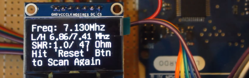
Since this is a no frills, unit, you are expected to grab the output from the Arduino and manually put it in a spreadsheet to plot the results. There is another version of the Arduino code that drives an OLED screen, although you still need a PC to kick the process off. One interesting feature of the Arduino code is how it deals with the nonlinear nature of the diodes used in the circuit. After plotting the values with known loads, [jmharvey] broke the diode operation into three regions and used different equations for each region. Even so, he warns that readings higher than 1:1 VSWR are only accurate to 10% or 20% – still good enough for ham shack use.
If you want an antenna analyzer for $40 (or less, if you have a good stock of parts) this looks like a worthwhile project. If, however, you want to repurpose it to Rickroll your neighbor’s AM radio, you might want to go with the commercial unit.
Click past the break to see the analyzer in action.


Very neat. Could you put a small LNA on the output of the RF generator to get the diodes up into their linear region? I know very little about RF.
I was thinking you could just DC bias the diodes, but that could be difficult. I haven’t really looked at it.
Forward biased conducting diodes won’t detect effectively in this application.
I wrote a Perl library to encapsulate the Arduino serial comms on windows.
The library automatically seeks out and opens the first Arduino it finds (or reports “none available”), and from that point it’s trivial to send and receive data to the micro.
A second library takes an array of numbers and pops up a line plot to show impedance versus frequency, or anything else you care to plot. Based on Tk::Chart.
Arduinos are remarkably versatile for taking measurements and otherwise sniffing around. If you set up the right tools, it’s trivial to make a quick one-off program to show whatever it is you want to measure.
(The frequency sweep thing will be available as part of my .io project, but I’m guessing that no one will want it because no one likes Perl.)
(And yes, my Perl code is perfectly readable by any coder. Perl doesn’t require unreadable syntax.)
Hams aren’t all cheap, we’re just all broke from buying overpriced transceivers and need to buy the other stuff cheap because our budgets are shot! :D
Just kidding, we really are all a bunch a cheapskates, which is why I’m so interested in this.
In case you haven’t noticed I’m WD5GNR and I’m at least as cheap as you are. Besides, you have to fly under the XYL radar.
Very true.
That whole, “We need to eat, so no more trips to HRO this month.” thing that they tend to say can really put a damper on things. :D
They sell off the internet you know; I’m just happy there isn’t a store in New Mexico.
I suppose I’m fairly cheap. But honestly, in the arena of antenna analyzers, I think there are a lot of advantages to building. I have an MFJ analyzer, actually just back from the shop, but I’ve built quite a few projects for analyzing antennas. None agree 100% with each other, but all are functionally adequate.
If my analyzer breaks again, I think it’s very likely that I won’t send it back for service a second time. It just isn’t enough better than what you can do yourself. If your own project breaks, you just fix it yourself.
Nope, not cheapskates–we just realize that we can build something just as good/functional as the commercial stuff. It’s also enjoyable to do so.
Well I’ve been a ham since 1977 and I’m just cheap ;) but yeah I also enjoy it.
I concur that transceiver prices are through the roof. Even used equipment is overvalued.
How about a peak detector instead of the diodes, like the LTC5507? Would that be able to provide better absolute results?
I was so thinking about building something exactly like this! Awesome idea.
My own family history is replete with radio “hackers” having risen to the highest levels of not only the hobby but the industry itself and dominates in the Southern half of this State. It sounds like I’m trying to drag out some fame or association for myself, but this is not the case. There is a already a well established and fully replete history of the radio industry including their names in this State. The ONE of incredible note is of advanced age and living comfortably and peacefully in the same home where he first climbed WPDR’s mast to replace the lamp, and was hooked, and became one of the most influential members of the industry. It is wished this continue for him in peace.
That being said… others of his family also went into other electronics and technical studies. There are two HIGHLY noted aviators, one and aircraft designer of world record, still active and producing world records. A very early computer mainframe programmer which you didn’t even know existed at the time…
Your progenitors that taught you are passing….
People, in the developing years of these industries, did HUGE things that forced us all forward into the future just as we hoped….. but they are passing.
As a nation, we look to you to make the next innovations. We look to you to take the next risks. It is up to you to make the next advances.
This family pushed the advances and sped the future to us…. but I am the wagging tail of the last of those with such impetus and insight…
… it is now up to all of you. I suggest there be a slant towards social responsibility to all your works… accomplishment does not always mean progress, but progress is the point.
I appreciate the sentiment and important points, but what does this have to do with the Arduino Antenna Analyzer article?
Is there any budget friendly way to scale this into the microwave frequencies, specifically WiFi 2.4Ghz/5.9Ghz?
I have the ardunio and a dozen failed WiFi antennas and I would love to revive that project.
Rather than an AD9850, look at the SI570 oscillator. It puts out square waves, so an 800 MHz signal *might* give you a useable signal at 2.4GHz.
5.9 GHz is a bit more of a stretch.
Guessing that wouldn’t be a drop in replacement?
2.41-2.48Ghz + 5.03-5.8Ghz (not 5.9Ghz like I incorrectly wrote) would be ideal but the preference would be the 5Ghz band honestly.
Sorry I have never done anything on this level before!
I’m sure there are a bunch of people laughing at the thought of me trying to hand tune a 5Ghz antenna with zero experience and zero way to measure the results…
If you want to tune a wifi antenna, you’d be better off using a wifi card as a signal generator(some ATH9k chips can generate a cw tone) and making your own directional coupler. Analog devices make a HF/VHF logarithmic amp like the AD8307 but there’s a family of similar chips that cover wifi frequencies.
Also apologies I didn’t thank you for your reply :)
You could use ADF4351 as 35MHz-4.4GHz signal source (dev boards on ebay for $45) and an 800-2500MHz 10dB directional coupler ($10 on ebay) to measure the reflections. You’ll probably have to use faster diodes as a detector (HSMS-28xx?).
To get to 6GHz, I would try HMC188 frequency doubler (ebay, $17, with pcb), but you might first have to amplify ADF output to 10dBm, possibly with one of those ‘$15 sdr lna’ boards, if they have sufficient gain at 3GHz. You can easily etch a (rather lossy) directional coupler on a PCB.
Can left top part of this circuit http://ludens.cl/Electron/HFantenna/AntSCH.gif be used to enhance VSWR detection?
Guy, that created this is actually tuning special antenna to transmitter.
I’m planning to build a DDS-based VFO in order to adapt an old crystal-controlled marine radiotelephone to the ham bands. I wonder if I could combine these two projects?
do you mean to have an antenna analyser in a radio? no that would not make sense. If you liked you could separate the vfo from both projects and share it between them but for the price of the vfo 9 dollars or so it’s not worth it.
You can’t use square waves as the generator source. The (broadband diode) detectors will detect voltages from the first few harmonics and mess up the results. So, the AD9850 oscillator will work but the Si570 will not, unless you carefully filter the output. Results will also usually improve with higher outputs than the output level available from the standard AD9850.
Further background on the method as well as a basic analog design can also be found at http://www.zl2pd.com/analogZmeter.html and (many) other websites describing antenna analyzer designs.
Do you have a full schematic including the wiring to the AD9850 and to the arduino?
see if this helps… https://github.com/jmharvey1/DDS_AD9850_AntennaAnalyzer
Yes I did see this and it gives some information but it does not include the LCD.
Did you ever think about making a schield for this? The schield layout is included in EAGLE.
I think I found the other pins in the arduino sketchs. Are these al the pins?
Pin 8 – connect to AD9850 module word load clock pin (CLK)
Pin 9 – connect to freq update pin (FQ)
Pin 10 – connect to serial data load pin (DATA)
Pin 11 – connect to reset pin (RST).
LCD U8GLIB_SH1106_128X64 u8g(3, 4, 7, 6 , 5); // SW SPI Com: CLK = 3, MOSI = 4, CS = 7, dc = 6, RES = 5
I made something like yours with a friend off me , but we use an correction amplifier so we have 17 dBm ( 50 mW) from 400 khz to 35 Mhz . We tested it with fixed attenuators and it worked fantastic . With this attenuators you can directly mesure the Return Loss as twice the value off the attenuator.
Looks interesting and will look at this myself in the Uk we say an Engineer is someone who does for £5 (pounds) what any fool does for £500
Very cool, thanks for posting. Got here for the first time via FB so not sure where you post the schematic or parts list.
I would like something similar that would enable me to tune a home-made Yagi for my 2-meter handheld. Is there a way to make this work for 144 – 148 MHz?
DDS module and an Arduino instead of dropping a few hundred dollars on a commercial unit. As he points out, you probably only need an analyzer for a day or two while you set up an antenna.
Cool! I agree wholeheartedly with the author with his viewpoints expressed here. A link to the complete project with schematics, list of parts and code would be great to enable newbies like me to get our hands wet.
p.s.: we aren’t cheapskates; we just abhor expensive, overpriced commercial equipmen! ;-)
schematic ? frequency range ? return loss range ?
I regard my question is the display NOKIA 5110 will serve me for this project
Participer pour amiloré logiciel : ZMATRIX Dévlopement link limited fontion
can somebody explain the formulas in following code of scatch
double CorrectReading(float ReadVal) {
if (ReadVal > 70)
return 0.8*ReadVal+57;
if (ReadVal < 13)
return 3.6*(ReadVal*ReadVal)/15;
float CalcVal=1.1*( 8+(2.1*ReadVal)-((ReadVal*ReadVal)*10.7/1000));
return CalcVal;
}