A Sneak Peek At Anechoic Chamber Testing

[Mathieu Stephan] has something new in the works, and while he isn’t ready to take the wraps off of it yet, he was kind enough to document his experience putting the mysterious new gadget through its paces inside an anechoic chamber. Considering the majority of us will never get inside of one of these rooms, much less have the opportunity to test our own hardware in one, he figured it was the least he could do.

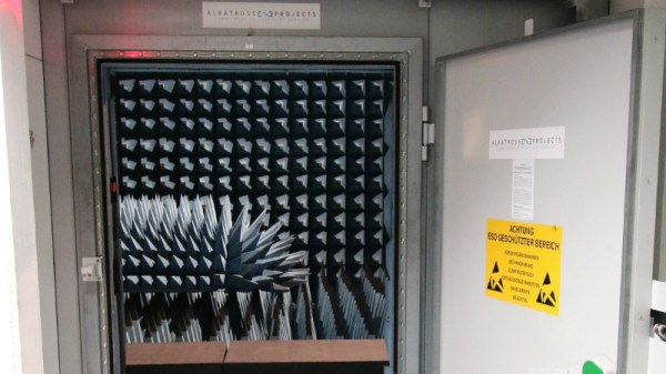
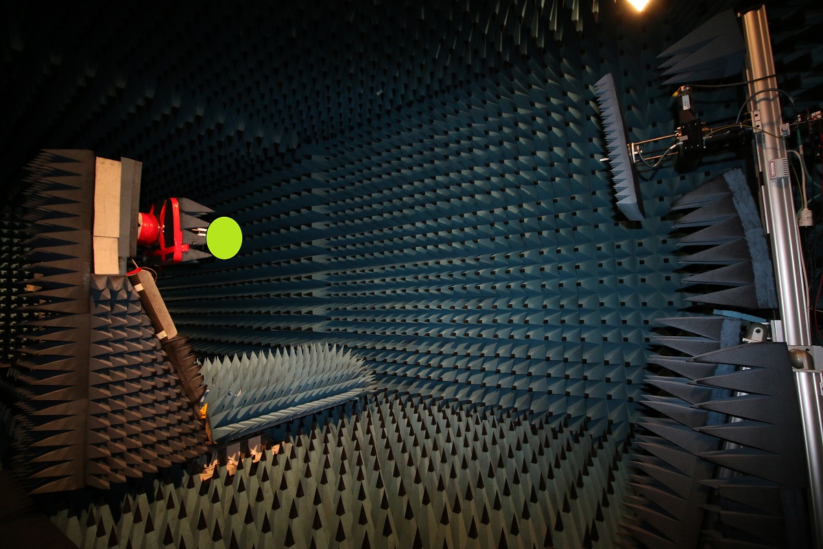
If you’re not familiar with an anechoic chamber, don’t feel bad. It’s not exactly the sort of thing you’ll have at the local makerspace. Put simply it’s a room designed to not only to remove echos on the inside, but also be completely isolated from the outside. But we aren’t just talking about sound deadening, the principle can also be adapted to work for electromagnetic waves. So not only is in the inside of the anechoic chamber audibly silent, it can also be radio silent.

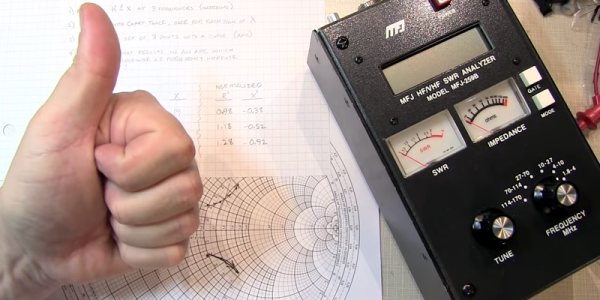
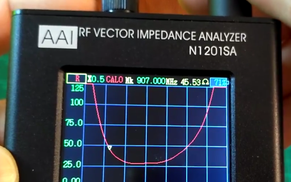
This is important if you want to test the performance of things like antennas, as it allows you to remove outside interference. As [Mathieu] explains, both the receiver and transmitter can be placed in the chamber and connected to a vector network analyzer (VNA). The device is able to quantify how much energy is being transferred between the two devices, but the results will only be accurate if that’s the only thing the VNA sees on its input port.

[Mathieu] can’t reveal images of the hardware or the results of the analysis because that would give too much away at this point, but he does provide the cleverly edited video after the break as well as some generic information on antenna analysis and the type of results one receives from this sort of testing. Our very own [Jenny List] has a bit more information on the subject if you’d like to continue to live vicariously through the accounts of others. For the rest of us, we’ll just have to settle for some chicken wire and a wooden crate.

Continue reading “A Sneak Peek At Anechoic Chamber Testing”

Sign Of The Smith Chart Times

The Smith chart is a staple for analyzing complex impedance. [W2AEW] notes that a lot of inexpensive test gear like the MFJ-259B gives you complex readings, but fails to provide the sign of the imaginary part of the complex number. That makes it difficult to plot the results on a Smith chart or carry out other analysis. As you might expect, though, he has a solution for you that you can see in the video, below.

A common method is to increase the frequency slightly. In a simple case, you’d expect the imaginary part — the reactance — to go down for a capacitive impedance and up for an inductive one. Unfortunately, this doesn’t apply in many common cases, including when you are measuring through a transmission line which is probably what most people are doing with this type of test gear.

Continue reading “Sign Of The Smith Chart Times”

Antenna Analyzer Is A Lab In A Box

There was a time when the measure of a transmitting radio antenna was having it light an incandescent bulb. A step up was a classic SWR/Power meter that showed you forward and reflected power. Over the years, a few other instruments have tried to provide a deeper look into antenna performance. However, the modern champion is the antenna analyzer which is a way of measuring vector impedance.

[Captain Science] did a review of an inexpensive N1201SA analyzer. This device is well under $200 from the usual Chinese sellers. The only thing a bit odd is the frequency range which is 140 MHz to 2700 MHz. For some extra money (about $80 or $100 more) you can drop the low-end frequency to just under 35 MHz.

Continue reading “Antenna Analyzer Is A Lab In A Box”

$40 Antenna Analyzer With Arduino And AD9850

If you are a hacker, you might consider ham radio operators as innovative. Most people, however, just see them as cheap. So it is no surprise that hams like [jmharvey] will build an antenna analyzer from a DDS module and an Arduino instead of dropping a few hundred dollars on a commercial unit. As he points out, you probably only need an analyzer for a day or two while you set up an antenna. Unless you are a big time antenna builder, the unit will then sit idle on the shelf (or will wind up on loan to hams even cheaper than you are).

The design is rooted in another proven design, but changed to take advantage of parts he happened to have on hand. Although the build is on a universal circuit board, [jmharvey] used Eagle to lay out the circuit as though it were a PCB. Since placement can be important with an RF circuit, this isn’t a bad idea. It’s always easier to move stuff around on the screen than on the perf board.

Since this is a no frills, unit, you are expected to grab the output from the Arduino and manually put it in a spreadsheet to plot the results. There is another version of the Arduino code that drives an OLED screen, although you still need a PC to kick the process off. One interesting feature of the Arduino code is how it deals with the nonlinear nature of the diodes used in the circuit. After plotting the values with known loads, [jmharvey] broke the diode operation into three regions and used different equations for each region. Even so, he warns that readings higher than 1:1 VSWR are only accurate to 10% or 20% – still good enough for ham shack use.

If you want an antenna analyzer for $40 (or less, if you have a good stock of parts) this looks like a worthwhile project. If, however, you want to repurpose it to Rickroll your neighbor’s AM radio, you might want to go with the commercial unit.

Click past the break to see the analyzer in action.

Continue reading “$40 Antenna Analyzer With Arduino And AD9850”

AM Chiptunes Played By A Modified Antenna Analyzer

Believe it or not, this VK5JST aerial analyzer kit is going to rickroll you. [Erich] wanted to see if he could use the device in a different way. His adventure led him to use it to feed different tones to an AM radio, producing the all too familiar [Rick Astley] offering.

There’s a fair bit of math that goes into getting the correct signals to generate a given pitch. But it basically boils down to patching into the hardware early in the RF generation. This way an audio signal can be rolled into the carrier frequency. Since this kit uses a PicAXE microcontroller with available source code it is rather easy to add audio input to tweak what the chip is putting out. But there is also some hardware tinkering to be done. Read more about that at the article linked above, and don’t forget to check out the bottom of that page to hear the final results.