[QRP Gaijin] likes to build regenerative receivers. If you’ve ever built a serious one, you know there are (at least) two problems: One is you need a variable capacitor (hard to find these days). The other annoyance is that if you cover a wide frequency range, you probably need more than one coil.
[QRP Gaijin’s] latest radio design doesn’t have either of these problems. He uses a coil with a single pole double throw switch to bandswitch a single coil. There is no traditional main tuning capacitor. Instead a 1SV149 varactor provides the radio’s main tuning capacity (the diode tunes between 35 to 500 pF).
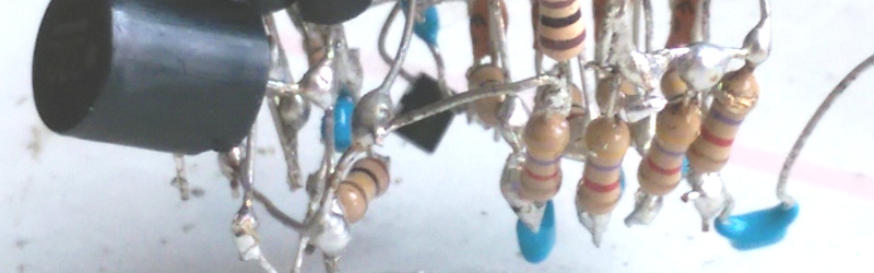
The post provides a nice design and a neat looking build in a Tupperware container (well… the outside is neat, at least; the inside is… best left inside the Tupperware). Better still, [QRP Gaijin’s] post details how he got to the final design, starting with the idea, and detailing the original design and the changes he made along the way. He also used data from an earlier build to limit how much the regeneration control has to be changed over wide frequencies and details how that changed the design. The prototype actually lacks the planned bandswitch, but will cover 3 to 30 MHz with the right coil.
There are certainly simpler regenerative receivers out there. However, the sophistication of this design along with the details of the designer’s thought processes makes this an interesting intermediate weekend project.


What I find most impressive about this is the construction method. I need a perfboard to hold anything and everything I build, and I still manage to screw most of it up. I could never put together a functional radio circuit that way.
Yes, I’m pretty mechanically inept myself, so I thought the same thing.
You can see some details of the construction technique (for the AF amp part) here: http://theradioboard.com/rb/viewtopic.php?t=5853 . It’s not so hard if you use one of those helping-hands dual-alligator-clip stands to hold the parts in place while you tack a blob of solder on the relevant leads.
Why the gloves?
chances are the metal in the knob is grounded. Not insulating the human from the tuning ground could have wonky side effects.
Frequency hertz.
Richard AKA Dick Hertz.
No real reason. Ideally my hands would not be in the video at all (using long wooden rods to rotate the knobs). I just like my technical videos to focus solely on the device in question and not on the operator. The set does work fine in practice even if operated without using gloves (no hand capacitance or hum).
Japanese Engineer? I have worked with them before (Species: NEC). All wore white gloves when working with equipment.
Variable caps can be had on aliexpress for less than $2. It is small, transistor-radio variety though.
It is also possible to make a variable cap. There are people who actually did that.
Variable capacitors are not hard to find:
http://www.mfjenterprises.com/catalog/mfj/MFJ_2015_Ham_Radio_Catalog.pdf
See page 86
>
Of course, you can source them and you can even yank them out of old radios. But the days when you could drop by Radio Shack and buy one are gone. Besides, having a varactor turning arrangement has other benefits like controlling the frequency by wire, for example.
Most “not defunct” electronic distributors sell variable caps.
And are temperature sensitive, and often require high reverse voltages, and on, and on… But they are easier to band-spread and you can get them with around a decade of capacitance range.
There are still tube radios that are free (or nearly free) in my area… especially heavily picked over chassis, or “farm sets” (Battery operated table radios) with severe cabinet damage/chassis rust issues. A nice, friendly-big variable cap should still be a guilt-free $5 or under proposition, without prying one out of grandma’s pristine catalin Fada Bullet.
I’ve been reading/hearing on amateur radio blogs/podcasts for a while that variable capacitors are suddenly hard to get. I don’t understand this at all. Ebay is full of them. A quick Google search will find you plenty of other sellers. I’ve found tons of them at recent hamfests and at those hamfests ‘ve noticed that the prices seem to be going down.
I do like varactors myself. I like that they let me keep my RF leads short and only run DC through the tuning knob thus eliminating the hand effect. I appreciate that design choice but I just don’t get why the ‘variable capacitors are becoming hard to find’ mantra keeps getting repeated. Is somebody trying to push the price up?
I wonder how much this receiver radiates from the antenna connection…
Good question. The transistor Q1 is a common-base RF amp so it should provide a reasonably good reverse isolation. In addition, I also tried connecting a tuned small loop antenna (~0.8m diameter) — remotely tuned with a 1SV149 varactor with signal pickup taken from a smaller coupling loop inside the larger loop — to the receiver, at the input of the common-base amp. Tuning of the tuned loop antenna had no pulling effect on the frequency of the regenerative detector (even when the antenna was tuned through the resonant frequency of the detector), indicating quite good isolation between the detector Q2 and the antenna, thanks to the isolating RF amp Q1. The same thing occurs when attaching a random wire antenna — no pulling of the detector frequency is noticeable when connecting the antenna. So, I would expect very low levels of radiation from the antenna. I’m not able right now to actually measure the radiation, but maybe I can try running an LTspice simulation to estimate the reverse isolation of Q1.
Is the schematic available?