Last month, I talked about how to get started with mBed and ARM processors using a very inexpensive development board. I wanted to revisit mBed, though, and show something with a little more substance. In particular, I often have a need for a simple and portable waveform generator. It doesn’t have to be too fancy or meet the same specs as some of the lab gear I have, but it should be easy to carry, power off USB, and work by itself when required.
My requirements mean I needed a slightly more capable board. In particular, I picked up a K64F board. This is very similar to the KL25Z board but has a bit more of everything–speed, memory, etc. What I really wanted, though, was the SD card slot. I did, however, do my early testing on a KL25Z, so if you have one, you can still work through the code, although standalone operation won’t be possible. The price jumps from $13 to $35, but you get a lot more capability for the price.
Project Overview
The K64F board has a CPU with a built in DAC (digital to analog converter). The output is on pin 11 of J4 (marked as DAC0_OUT on the pin out picture that comes with the board). The USB serial connection to the board will allow you to send commands and data to the board. The commands are pretty simple:
- l – Load a decimal file by serial port (16K entries ranging from 0 to 65535)
- x – Load a hex file by serial port (16K entries ranging from 0 to FFFF)
- f – Load a floating point file by serial port (16K entries from -1 to 1)
- t – Set the timebase in microseconds (floating point)
- z – Zap the memory with either one value or two alternating values (good for testing)
- d – Show directory of SD card
- r – Read file from SD card
- w – Write file to SD card
- g – Generate output (reset to return to prompt)
If you read or write a file with a .cfg extension (actually, any extension that starts with a C), the device will read or write the data and timebase in a special file format. Any other extension is expected to be a binary dump of the data using 16-bit unsigned integers.
When the board resets, it will look for autowave.cfg in the root of the SD card. If found, it will load it and execute immediately unless you hold down the S2 button during restart. If the button is down or the file isn’t there, the board prompts you and waits for a command. If you have an autowave.cfg file, the board will work without a connection to a PC (just supply power).
You can easily generate interesting waveforms using TTI’s Wave Manager Plus software. Since some of you won’t want to register to download the software, you can also use a spreadsheet or text editor, but it is harder to make complex waveforms by hand. The TTI software is for Windows, but I’ve run it under Wine with no trouble (check out the video below for a full demo of using the software with this board).


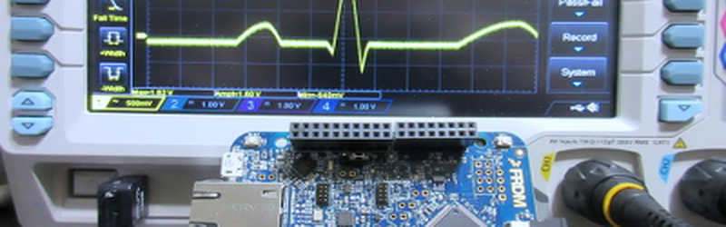
For example, the image to the left is a “cardiac” wave form made with the TTI software. It was exported in NRM format and then read with the F command. The picture on the right shows the resulting output (along with a little bit of the last waveform and a bit of the next one, too). Once a waveform is loaded, it is wise to save it to the SD card since that is much faster to load in the future. The serial port is only 57600 baud, and there’s a good bit of data to push through (the program uses a 16K buffer of 16-bit data).
The project doesn’t require any external hardware unless you need to filter the DAC output. For what I needed, it was perfectly fine just the way it is. When you use the G command, the board will output a 16-bit value to the DAC, wait for the time specified in the timebase, and then move to the next value.
Getting Started
If you haven’t used mBed before, you might want to revisit our earlier tutorial. Otherwise, jump over to the online project, if you like. Note the platform is set for the larger board. If you want to use a smaller board, you’ll probably have to reduce the buffer size and turn off the SD card (all done in main.h). You will also have to change the project to use your board and probably have to recalibrate the timebase (see below).
Unlike the starter project I showed you last time, this one has a good number of files. However, most of them contain just good old C or C++ code. There’s only a few special items required that are mBed specific.
File Orientation
Before we look at the mBed specific code, let’s get the layout of the program in general. There are five C files (and their associated headers). There are also two libraries: the mBed library and one for SD card access. This library came from searching the import button in the mBed IDE.
Here’s the files that make up the program:
- main – A very simple main program resides here. The header has some global configuration data.
- cio – Character oriented (serial port) I/O. Helpers can read integers, floats, etc.
- command – The command processor that lets you interact with the program.
- output – Drives the analog output and deals with timing.
- sdcard – Simple interface to the SD card file system.
Although the files all end in .cpp, I didn’t use much C++ in the actual program (outside of C++ comments and maybe some default parameters). What I did use, though, is C++ objects provided by the libraries to make life much easier.
Library Support
The mBed library takes care of all the board-specific setup (clock, power, etc.). It also provides C++ objects for digital inputs (the autostart override switch), the DAC, the serial port, and a lot of other functions on the board we aren’t using.
The library is well thought out. For example, the serial port is nothing more than this (in main.cpp):
// Serial port
Serial pc(USBTX, USBRX);
Using it is simple:
 pc.baud(BAUD); // set baudrate
 pc.printf("Hello World\r\n");
The digital input is easy too:
// Switch to suppress auto loading
DigitalIn NoBoot(SW2);
Reading it is a snap:
if (NoBoot==1) auto_open();
Unsurprisingly, the DAC is just as easy:
AnalogOut aout(DAC0_OUT); // Analog output
aout.write_u16(buffer[bp]);
The only thing that the library fails at is timing. There are a variety of timing mechanisms available, but none of them have good characteristics below a few dozen microseconds. So I didn’t use the library timing components.
You’d think the SD card access would be complicated. Thanks to the nice library, it isn’t complicated at all. There’s the usual set of functions like fopen, fclose, fread, fwrite, etc. The only hitch is knowing that all the files appear to be in a directory called /sd (you can change that).
Here’s the setup for the SD card access:
SDFileSystem sd(PTE3, PTE1, PTE2, PTE4, "sd"); // MOSI, MISO, SCK, CS
That’s it. Once you import the library, your project explorer on the left side of the screen will have documentation nodes for the library so you can read about available functions and find example code. Although the SDFileSystem object is well documented, the underlying FATFileSystem doesn’t have a documentation node (but you can read the comments in the source code). However, as the example code shows, it is pretty much the standard C file calls you’d use almost anywhere else:
// worker for directory listing (call from file prompt too)
uint32_t do_list(const char *fsrc)
{
#if SDCARD==1
 DIR *d = opendir(fsrc);
 struct dirent *p;
 uint32_t counter = 0;

while ((p = readdir(d)) != NULL) {
 counter++;
 printf("%s\r\n", p->d_name);
 }
 closedir(d);
 return counter;
#else
 return 0;
#endif
}
So access to the SD card is pretty anti-climatic. You might think all this takes up a lot of program space. It does occupy some space, of course, but according to the build tool, I’m using about 42K of my 1M of flash memory. So plenty of room to do more things.
Driving Output
I experimented some with doing DDS-style output ([Bil Herd] did a great post on DDS), but finally decided to keep it simple. The output module has two execution kernels. Once either of them starts running, the processor does nothing but generates the output waveform until you reset the system. This side steps having to worry about timing of the output while other things are going on. One kernel handles the case where the timebase is set to zero (indicating that the CPU should go as fast as it can). The other handles the case where you expect the program to output a sample from the buffer, delay a certain amount of time, and then output the next sample.
As I mentioned earlier, there is a significant problem, though. The mBed library has periodic and one shot timers that are very easy to use. They also don’t do well below a certain time (on the KL25Z, that time was about 26 microseconds). There’s quite a bit of discussion about this on the mBed discussion boards, but ultimately it is difficult to get very short timers without a lot of jitter through the library.
Since the output routines monopolize the CPU, I did some experiments in changing the programmable interval timer, which you can do in mBed:
// assume by here the PITs are ours
SIM->SCGC6|=SIM_SCGC6_PIT_MASK;
 PIT->MCR=0;
 PIT->CHANNEL[0].LDVAL=0xFFFFFFFF;
 PIT->CHANNEL[0].TCTRL=PIT_TCTRL_TEN_MASK;
...
 counts=PIT->CHANNEL[0].CVAL;
...
 counts=~counts; // convert to count up
 counts+=110; // how many ticks before we proceed (40nS per + overhead)
 do {
 clock=~PIT->CHANNEL[0].CVAL;
 } while (clock-counts>=0x80000000UL);
 nop(); nop(); nop(); nop(); // fine tune delay
 }
In the end, I didn’t really like this approach. It required some tweaking and was also not necessarily portable to other platforms. If this were an assembly language program, I could count cycles, but I decided to take a different tack. You can, by the way, embed assembly in mBed very easily. See the nop calls in the code above? Here’s the definition in output.cpp:
// inline assembly for nop (plus function call overhead)
void nop(void)
{
 __ASM volatile("nop\n");
}
You could also send the buffer words to output pins if you wanted a digital pattern generator. The only problem is the board doesn’t have 16 pins all on one port easily accessible. The mBed library will let you write to virtual ports that aggregate pins from different ports, but the performance of that is not good. However, if you needed a pattern generator with no more bits than you could find spare on the edge connector that belong to a single port, a simple change to output.cpp would do the trick (that is, write to the port instead of the DAC).
Timing Calibration
The exec function in output.cpp essentially executes some nop calls in a for loop to get the delay. This leads to the question: how many times through the loop do you need to get a particular time? To answer that, I added a temporary calibration mode and hooked the device up to a scope.
By default, on each restart (when there is no autoloaded waveform), the memory is filled with two repeating words: 0xAAAA and 0x5555 (you could change this, by the way, in command.cpp). In calibration mode, you can set the timebase to some number and measure the resulting time it takes for the signal to make one transition. In other words, you’ll get something like a small square wave and you need to know the time it takes for the high or low part of the square wave to execute. Try a few different values for the timebase and make a table.
| T | Measured Time |
| 1 | 0.328uS |
| 100 | 4.67uS |
| 200 | 8.8uS |
| 1000 | 42.4uS |
The idea is to do a linear curve fit on the data, come up with a slope and an offset (remember y=mx+b?), and plug that into the program. Then turn calibration off, recompile, and you are done. It would be hard to do this calibration without a scope, although you could use larger values of T to get the time scaled up if you have a low-bandwidth scope.
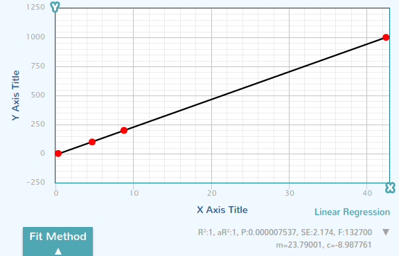 If you don’t remember how to do a linear curve fit and you don’t have a calculator handy, try this cool website. You can see part of my session and read off the slope (23.79) and the offset (-8.98) to the right. Note the R is equal to 1 which means the curve fit is good. If R were much less than 1, you probably should double check your data to make sure it is correct.
The M and B constants are in output.cpp and the program uses this (in non-calibration mode) to convert your timebase in microseconds into an integer number of counts. It isn’t always perfect, but it is pretty good and the floating point math support in the compiler makes this easy. Of course, floating point math isn’t always good when it comes to performance, but none of the non-integer math occurs inside the critical timing loops.
The only thing to remember is that if the exec loop changes, you need to recalibrate. This does bring up one of the problems of using an online IDE. Although it isn’t likely, a recompile could change the exec loop even if you didn’t touch it. An upgrade to the compiler or a change in its options could happen at any time and you aren’t really aware of it. If you were running a local compiler (and, by the way, you can) then you’d know if you changed anything and if this were an important project you could version control the compiler and libraries and options yourself.
Keep in mind, the timing isn’t going to match some lab-grade instrument. There are certainly techniques you could use to drive down the error if you wanted to. On the other hand, the DAC settling time means you aren’t going to get super sharp square waves anyway. For the device’s purpose, this timing scheme is perfectly adequate.
Tips and Tidbits
If you use Chrome and you can’t see the text in the mBed editor very well, you might want to check out the Chrome store. The mBed++ extension allows you to set the text size. The only thing I found disconcerting about it was that when you selected text it would shrink back to the normal size. Still, it makes the environment a little more friendly.
This isn’t actually an mBed tip, but when I was talking about the PIT timers, did you notice the test to see if the time period completed? Here’s a paraphrase using 16 bits instead of 32:
unsigned short counts, clock;
counts=get_current_tick()+0x100;  // A
do {
     clock=get_current_tick();
     } while (clock-counts>=0x8000U);
If you haven’t seen that before, it is a nice trick that allows you to detect when clock is greater than or equal to counts even if the clock has rolled over. In other words, this handles the case where the start clock plus the offset (counts) doesn’t overflow (for example, if at point A current_tick returns 0x100 and counts becomes 0x200) and the case where it does (say, if current_tick returns 0xFFF0 and counts becomes 0x00F0). This assumes, of course, you look at it often enough that it can’t wrap around twice in between tests which is not a problem in this case.
Wrap Up
This was a little more involved than a blink the LED program (or change LED colors, if you consider the last mBed post). I wanted to give you a taste of doing something at least somewhat practical with these boards. Perhaps the most amazing part of it is that it isn’t all that amazing. There’s a perception that the Arduino, as an example, is somehow easier to program. It is easy to program, primarily due to the many libraries with documentation and example code. However, systems like mBed are getting pretty close to having good library support too. It also makes life a lot simpler to have a 32-bit processor with lots of memory and a high clock speed.
You might also argue that the Arduino has so many daughter boards (it pains me to say shields). However, many of the mBed boards (including all the ones I’ve mentioned in this post) have sockets that can handle many shields (remember, these are 3.3V boards, so plan accordingly).
Not to knock the Arduino. However, it seems to me that with a more powerful processor, good library support, a simple IDE (and an upgrade path if I want something more sophisticated like Eclipse and debugging) these boards and chips will continue to infringe on the Arduino’s turf.
Between the last post and this one, you don’t have much excuse not to try it. There’s no software to install. An LPC1114 will fit in a breadboard and is very cheap if you already have a USB to serial adapter. The Freescale boards mentioned in this project start at less than $20. There’s nothing to keep you from 32-bit development.
By the way, if you decide to attempt this project and you want some ready made data files for your SD card, you can get them from my Google drive.


This gives me new respect for the mBed platform. That’s a lot of functionality for not that much coding. Obviously you know what you’re doing which made it go a lot faster… but still quite impressive. I’ll have to dig out the kl25z I have around here somewhere and see how much I can replicate on that less-feature-packed board.
Something like this could be done using PIT to set the sample rate + DMA cycle stealing in about 60 lines of code.
The 60 lines for the DAC transfer. The KL series has a simple DMA which is actually very easy to use just by reading the user manual.
.
Yes, I actually thought about going that route (and I do have a version that uses the PIT). But I decided this way was a better illustration of how you mBed is similar to Arduino in the variety of libraries and how you use them. That is one thing I like about mBed, though, is that I can export it to an IDE with debugging (sometimes, anyway) and I can dive into the chip level stuff as much as I want (or as little as I want).
This met my needs and I thought it made a better introductory sample program.
I want to do that on a KL25Z with Mbed… having *real* issues finding the documentation to get off the ground. I found https://community.nxp.com/t5/Kinetis-Microcontrollers/DAC-KL25Z/td-p/644289 and a load of stuff pointing at manuals (404) but I guess I’m going to have to read some header files…
I confess to being particularly familiar with Mbed (more of a *nix guy these days) but I’ve been forced into it, and in any case, am looking forward to getting my soldering iron out!
Im not sure if I missed it but what is the highest sine/square frequency. Not intrested in embed but i may replicate this project based on budget alone if the frequency is good enough
I avoided mentioning the frequency because it depends on how many samples you want per waveform. You can get sub microsecond time per sample (with some constant error, but you can factor that out). So in theory, you could make a square wave with 1us on and 1us off (period=2us) or less. So better than 500kHz. However, that’s misleading for two reasons. First, the DAC response time is not ideal for very fast squares so that will have some effect on your rise and fall (this really isn’t a digital generator–you’d be better off changing it to have digital outputs for that). The other thing is that for a sine wave, you’d want more samples per cycle than 2. So the question is how many samples per cycle do you want and then figure you can do 1uS per sample or less and you can figure it out.
If you watch the video, you’ll see, for example, where I put 2 cycles in one “waveform”. That has half the resolution of a single cycle, but twice the frequency. With the 16K buffer you could easily cram in a lot more than 2 cycles, but each time you do, your resolution will go down until it is unacceptable. Keep in mind, I’m running at 20uS per step in the videos just to keep things slow, but it will go much faster than that.
So this cant top cheesy 2mhz function gen, that is without bolthing some chips and a DDS on? If you would have told me 10mhz everything I woulda dived in an bought an mBed :)
Maybe best to diy it with an fpga, or micro with pwm, or micro with a dds (LTC6903/DS1086/etc), but know if anyone already sells a low-cost 1khz-100mhz clock generator?
pwm definitely need in my purpose
Hello!
Could this work with the LPC1768 version connected to a SD card?
Thank you,
Diego
It should if you have the mBed library either available for it or you are wiling to build it.
If you want to take a good deal from this post then you have to apply these strategies to your won weblog.