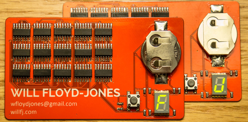
Having seen a number of PCB business cards [Will] decided to go against the more popular choice of a micro-controller based design and show some character with a logic based finite state machine. [Will] uses a single 7-segment display to scroll through the letters of his name with a state machine that outputs the desired combination of 1’s and 0’s to the LED display each time the tactile button is pushed.
[Will] uses a 4-bit counter made up of D Flip-Flops for the clock signal as a conditional input to 6 of the 4-input AND gates. He doesn’t go into the painful details of displaying each character through the process (thankfully) but he does mention that he uses the Quine-McCluskey technique for reduction instead of Boolean algebra. Since his name is 11 characters long and the 4-bit binary counter goes from 0000 to 1111 leaving 5 more pushes of the button before rolling the count back to 0000, during which time the display is left blank. [Will] kindly includes the eagle and Gerber files for your downloading pleasure over at his blog if you’re interested in getting a little deeper into the design.
[Will] went with boards 0.8mm thin instead of the standard 1.6mm which affords more thickness for the surface mount parts. The BOM totals: 15 ICs, a coin cell battery, a push button, 7 current limiting resistors, and a capacitor as a hardware debounce. [Will] assembled them himself by hand placing the SMD components and left the soldering to his Reflow Château.
The use of logic gates instead of a micro-controller shows some understanding of logic based design, which is a bit rare when compared to hobbyists with some micro-controller knowledge. Not to say that the PCB business cards that include a micro aren’t impressive in their own right. If you need to brush up your logic chops there are a few recent posts that you might find useful: [Bil Herd’s] logic series, and [Al Williams] covered a browser based logic discussion of flip-flops.


>The use of logic gates instead of a micro-controller shows some understanding of logic based design, which is a bit rare when compared to hobbyists with some micro-controller knowledge.
Logic circuits and reduction techniques are taught at pretty much any serious engineering programme (IT, robotics, electrical engineering and so on…). Nice PCB and pretty much nothing else.
Except that the school-taught reduction techniques are pretty much useless in the real world, where you have many other constraints than just minimizing sum of products.
Putting a pile of older technology chips might impress the crowd on youtube who are into building old 8-bit class computers, but not to your interviewers who expect you to have all the up to date skills and buzz words.
From cost/part count, you are stuck at 1980’s thinking using discrete logic gates. Anytime you are using more than 2-3 mickey mouse logic parts, you are better off using a small CPLD from a parts count, MTBF, BOM, flexibility point of view. You should at least shows some initiative to keep up to date with FPGA or at least use a CPLD using HDL and simulation tools. Even some firmware skill would be been better.
I think his message is received loud and clear: “I’m an educated computer engineer, not some dude who learned just by watching youtube videos.”
I wouldn’t hire the first guy unless he started as the second guy, but skills without knowledge very closely resemble flailing from the long term perspective. Being able to make a Theremin from an STM32F1 is equally important to being able to do the same thing from a 555 timer.
Gluing oversized SOCs to fiberglass with solderpaste doesn’t measure skill.
I used to have a professor that taught digital design. He usedthe phrase “mickey mouse” stuff when he was describing logic gates. This is exactly that – “Mickey Mouse stuff”. This stuff is taught at a 100 level engineering school.
wow
such elitism
very educate
while interesting, this is another example of an impractical business card.
Not if it scores you a big job
true that
+1
These business cards WORK. I made something similar, and even though they cost me $10 per card, half of the cards I handed out at least got me interviews, and multiple resulted in job offers.
Have you specced out business cards? There are so many options for aesthetic fluff that make this look practical in comparison: edge finish, embossing, card stock composition, raised print, metallic print, fonts and graphics, and all manner of colors for stock and print.
Business cards are meant to stand out, and Will’s is likely to stay on top of someone’s desk and not end up in the bottom of a filing cabinet.
Bin
I just copy the essential business card information in my phone, and throw away the actual card, especially if it’s some odd size.
All the more reason to make something that stands out and speaks to your skills to keep from getting filed away or thrown out (or both I guess)
Not really, because I wouldn’t have any interest in keeping such a gimmicky thing. If you want to impress me, show me some real boards. And they better have decoupling caps, and nicer routing.
Artenz, cut me a little slack! This type of discouragement is absolutely not what this community is about. And I’m only an undergrad, after all. It’s certainly not the easiest board to route beautifully. But soon enough, you’ll see some real boards from me, because I’m working on some awesome projects.
wow you’re handing me a piece of tech garbage that can’t be recycled easily. All I need is your name, a phone and/or email anyway – just send them to me with your mobile.
If you’re the sort of person who believes this is garbage, I can’t imagine you being the sort of person I’d want to work for.
True Chief
Fsckin-A, Will.
Bad-@$$ reply.
Fsckin-A.
Before I saw the gif I was wondering how he would put the letter W in a seven segment display.
Me too.
As did I.
I actually attempted to go for something like this at first: http://www.digikey.com/product-detail/en/QBASS40YG1/1516-1021-1-ND/4814748
But there were a few problems with this. (1) The logic no longer fit on the top side of the card (2) I couldn’t get samples for this part and they are expensive! (3) Using my 4-bit counter, I would only be able to fit one space into WiLLFLoyd-JonES_ either between my first and last name, or between my last and first name.
Yes, Union Jack LEDs can be expensive
e.g.
http://www.aliexpress.com/item/Free-shipping-10Pcs-lot-Wholesale-0-4-inch-2Digits-14-Fourteen-Segment-Red-LED-Alphanumeric-Union/760460760.html?spm=2114.01020208.3.100.CNPpWp&ws_ab_test=201556_2,201527_4_71_72_73_74_75,0_0
If you don’t press the button when it’s on, say, “F”, does it stay that way til the battery runs down? In about 15 minutes, I’d guess. And even then the whole thing’s constantly powered on? Good job his details are silk-screened on there too.
It looks like the battery goes directly to the button, so no press = no power.
no, it doesn’t. the button goes through a simple RC filter to debounce it, and that feeds the ripply carry 4 bit counter. the chips are all powered so long as the battery is in the holder. he mentions that if you “park” it on a space, the battery will last about 100 days.
Ah, not so bad. Still, maybe a 555 in there to cut the power would’ve helped, if you forget to park it.
Driving a clock with a slow rising edge. If anything, you should clean up the slow clock edges with a schmitt trigger.
Most logic design these days emphasis on synchronous logic. Asynchronous logic would create giltches as the clock propagates down the chain and your combinational logic decoder. There are no power on reset on a state machine.
So 3/3 of the no-no on a design. *face palm* This is how you should not design a state machine.
It’s absolutely not an optimal design, and not the way I would have implemented it on an FPGA. But it meets my design goals, works just fine, and had to be built using parts for which I could get samples. If you intend to be critical, you should also learn how to construct intelligible sentences.
You’re absolutely right, sorry about that tekkieneet.
It would probably last about 12 hours if it were left on F. It’s a 330 mAH battery.
Large number of chips without ANY decoupling caps and bulk for a high impedance lithium coin cell = automatic fail in my book. The passive around the display, you can at least line them up. Could use a bit better routing there too. They just look like the person has given up.
Remember that this is your first impression and you have practically unlimited time to do it. Why not do it right?
It is a really bad idea to short a capacitor through a button, like this guy is doing. I don’t know the current running through the button, but it could be several amps and the button will wear out way sooner than expected. I know this from experience ;-)
It’s only 450 nJ.
What this shows me is your initiative is there.
That’s good.
What would IMPRESS ME would be a COB processor on a flex circuit business card with an e-paper display and an energy harvesting power source with ESD sensitive parts covered in a sealant.
That is super cool! Thanks so much for sharing Will!
He might want to ask for it back after a month or two; otherwise, make 50 more by hand.
Actually I see a whole lot of good stuff here and a few minor problems.
One issue that I haven’t seen mentioned here (and perhaps I’m mis-reading the schematic) but there appear to be 3 unused gates. You need to tie all unused inputs off (usually to ground). With CMOS, unused inputs have a tendency to float to an intermediate voltage which turns BOTH input transistors on halfway, and that extra current draw can eat into your battery standby current.
The thing I *like* about this design is that it gives me something to talk with him about, for example during a job interview. This is a more than adequate design and Will has done a good job of addressing questions about his design in the comments here on Hackaday.
After explaining his card I’d ask him what things he did right, and what he did wrong…how he learned from mistakes and what different approaches he’d take. I’d learn a whole lot about him from those “what would you differently” sort of questions.
The board shouldn’t be red, it should be eggshell. And how are you going to implement Pale Nimbus (or even Romalian type) on a 7-segment display? It may as well be Silian Rail as far as the whole design aesthetic goes.
https://www.youtube.com/watch?v=cISYzA36-ZY
I see Will got a bit flustered by all the drive-by geeknasty. Actually though, Will… study ALL the attacks. Anyone you want to work for will have comments. At least, thanks to HaD flak, you can prepare for the worst. Get your frustrations out with these boneheads and familiarize yourself with even the silliest of their comments and you will be prepared like a rock star closing out a world tour! ;-/
Your card isn’t what >I’d< do either! But you are not me.
Good luck, Bud!