We’ve all been there. You’re building up a microcontroller project and you wish that you could just add “one more feature” but you’re limited by the hardware. Time to start thinking. (Or, arguably, buy the next model up.)
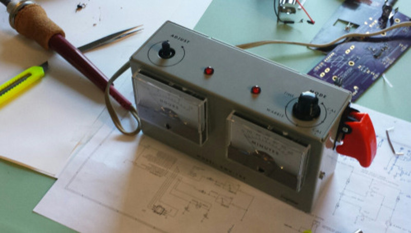
[Sam Feller] found himself in this position, adding a knob to set the time and a button to arm the alarm for his Analog Voltmeter Clock, and he came up with a way to implement an on-off switch, and poll a button and a potentiometer with only two pins of a microcontroller.
The problem with potentiometers in low-power designs is that they’re always leaking power. That is, unless you switch them off when you’re not using them. So the ideal solution is to power the potentiometer from one GPIO pin on the microcontroller, and read its value with another. That’s two GPIO pins just for the potentiometer. But [Sam] needed to read input from a button too, and he was out of pins.


His clever solution is to switch two resistors in or out of the circuit depending on the status of the pushbutton, so that the voltage range at the potentiometer is between either VCC and VCC/2 when the switch is pressed, or between VCC/2 and GND when the switch is not pressed.
If the ADC reads something higher than VCC/2, the microcontroller knows that the button is pressed, and vice-versa. The potentiometer’s setting determines exactly where the voltage lies within either range.
Done and done. If you find yourself in the similar situation of needing to read in values from a whole bunch of buttons instead of a potentiometer, then you can try using an R-2R DAC wired up to the pushbuttons and reading the (analog) value to figure out which buttons are pressed. (If you squint your eyes just right, this solution is the same as the R-2R DAC one with the potentiometer replacing all but the most-significant bit of the R-2R DAC.)
Another tool for the toolbox. Thanks [Sam].


If the analogue input pot only needed to be read in a particular state then this maybe could be done with 1 input. Pot with resistor both sides so it never goes all the way up or all the way down, one switch could short across it and the other could open the circuit. Depends on the exact usage intention of course.
Ok, so having to press the poll button after using the alarm on/off switch would be annoying. I have a new plan. For my next trick I will wire a DPDT switch with 2 capacitors and 2 resistors such that any throw will result in an RC decay curve the MCU could use to tell the on and off events apart from each other, the press of the poll button and the resulting read of the potentiometer. Ok now that’s a system with a switch, a poll button and a potentiometer that only draws current when a button is pressed or the switch is thrown and only uses 1 GPIO. The main drawback like before is that the poll button must be pressed to read the pot, but there is no whole ADC bit lost like with an R2R network solution.
For the cost of a mechanic switch you could upgrade to the next better microcontroller with more io pins.
Or add an 8-pin micro just to do the switch reading, connected through serial to your main one. They’re so cheap you can do stuff like that.
There’s a very simple means to read a pot without an ADC without consuming any power.
You set the pot in series with a small capacitor, and time how long it takes to change it from low to high logic level when being charged up through one of the GPIO pins. When you set a GPIO pin as input with internal pull-up, it does that for you automatically. When not actively reading, you set the pin as output at a low logic level, the capacitor is discharged.
That is, without consuming any power when -not- measuring the pot. Of course it takes some power to charge up and discharge the capacitor.
You do not need a10.000uF cap, you can do this with 1nF, so we are talking about nano Coulombs, that is 0 compared to the rest of the device
Also, you can use the same GPIO pin simultanoeusly as a generic button by simply shorting the capacitor with the button. That way, when the software times out without ever seeing a logic high, it concludes that the button was pressed.
You can add a second button to pull the logic level high, and assuming there’s a minimum delay in the pot-cap, you can test whether the logic level is immediately high, so it is possible to have two buttons and a potentiometer in a single GPIO pin.
Actually, refining the idea:
1) set up one GPIO pin as a high-z input without pull-up.
2) connect the potentiometer with a series resistance as the pull-up
3) connect a capacitor between the pin and ground
4) connect a button across the capacitor
5) connect a button with a low-value resistor across the potentiometer
Now every time you want to measure the state of the system, you set the pin as a low output for a bit to discharge the capacitor, then set it to input again and measure how long it takes for the input to reach logical high. If it’s very fast then the high side button was pressed. If it times out, the low side button was pressed. If it takes something in between, that’s the value of the potentiometer.
This is a very nice solution. Thanks :)
+1, the MCU output needs to be short tolerent but that is awesome.
You can add a resistor between the capacitor and the MCU because the high-z input state draws little to no current – it’s just measuring voltage.
Basically, if you’re talking about a typical micro that recognizes about 2/3 the VCC as logic high, the behaviour of the RC system is more or less linear. The capacitor fills up at a linear rate up to about ~63% of the input voltage before it starts to taper off, so, you can run a simple busy loop or timer and an interrupt and get the position of the pot down to very high precision, 10 bits, 12 bits easily.
The downside is that it takes about 4000 cycles to measure it at that precision, which is why you probably want to use an interrupt and a timer.
That’s a lot like the old voltage-to-time convertors. Lots of computers used this, particularly because it’s so cheap, just 1 capacitor and a digital I/O line. The IBM PC joystick ports used it, as did the Atari 2600’s paddles.
Timing an RC delay is a legitimate way to do analog-to-digital conversion. The buttons are simply corner cases of having the input at V+ or ground.
The buttons on what? Not on the old PC joysticks, there were 2 digital inputs provided for buttons. The 15-pin port was designed to support 2 joysticks, with presumably some kind of splitter cable, so there were actually 4 axes and 4 buttons altogether. Some of the 8-button Playstation-style joypads, just before USB, used the axes of Stick 2 to provide an extra 4 buttons.
Later on, they actually added a UART to the joystick port for digital joysticks that can support a lot more axes and buttons as well as force feedback. It just didn’t catch on before USB took over.
Didn’t know that! Is this back when they were inventing ECP and EPP and stuff? Abusing the parallel port was the USB of it’s day! Still, Soundblasters started the idea of putting MIDI through the joystick port, that’s a serial data stream, if it was me I’d have taken advantage of that. It’s something like 56Kbps. You don’t HAVE to send music data through it.
My experience with micros … If you need more pins just get micro with more pins. It will cost you few cents more, your time and additional components for hacking smaller micro will cost you more. However hack like this is nice to see, there is always “you’re trapped on a space station with very limited resources, think your way out of the situation” scenario where solving problems like this saves a day, and yourself.
The case is usually that you’ve got your drawers full of some particular micro you got cheap from an ebay offer, or some other “ooh that’s a great deal”, and you want to make do.
Obtaining the “few cents more” micro in single units usually costs you ten bucks in postage, so it’s highly inefficient to buy it just for that one project, just because you wanted one more GPIO.
Microchip had some handy guides of tips and tricks for getting the most out of small microcontrollers.
http://ww1.microchip.com/downloads/en/DeviceDoc/01146B.pdf
That’s a cool app note, thanks!
Finally! A clock project! :-)
Another way with just one pin, use a piezo microphone and do all your command with voice.
Or plug a IR sensor and use your favorite TV remote with many buttons
OR, wire two of these junk-drawer micros together.
… or pick up a $2 esp8266 from fleabay.. (why do I keep wanting to call the esp8266 an 8255.. probably because I’m an old enough fart to know what an 8255 is/was ) with built in wifi … but none of these suggestions is as much fun as figuring out how make do with what is in the parts bins in front of you.
But using what’s on hand is exactly what I was suggesting. Even the most minimal micro can be used as I/O expansion for another.
i did not bring this, because of the low power feel of the project, and with an average of 70mA the esp is not the perfect choice. But it’s surely the best way to add a nice user interface to any device.
Or… one pin drives a shift register which in turn pulls up switches, potentiometers etc and the other, set as analog input with a single pull down resistor, reads the value. When in power saving mode you just set the shift register to a pin with nothing attached.