Consumer 3D printers have really opened up the floodgates to personal at home fabrication. Even the cheapest of 3D printers will yield functional parts — however the quality of the print varies quite a lot. One of the biggest downfalls to affordable 3D printers is the cost cutting of crucial parts, like the z-Axis. Almost all consumer 3D printers use standard threaded rod for the z-axis, which should really use a leadscrew instead.
Threaded rod is not designed for accurate positioning — it’s primarily designed to be a fastener. You can have issues with backlash, wobble, and they usually aren’t even perfectly straight — not to mention they gunk up easily with dirt and grime. In other words, you’ll never see a threaded rod on a commercial machine.
 Enter the lead screw. Lead screws are precision machined components used for pretty much all proper CNC equipment. They have almost no backlash, they’re perfectly straight, and they allow for higher load transfers without jamming.
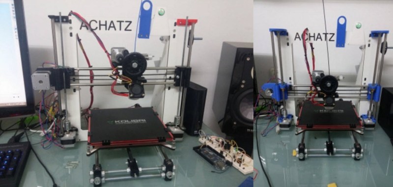
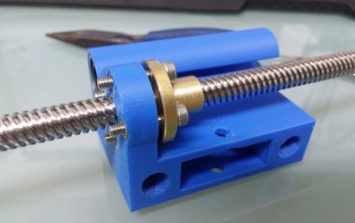
In order to upgrade his Prusa i3, [Daniel] designed and printed his own z-axis carriages to use with the lead screw.
If you have a Prusa i3 too, he’s uploaded the design files to Thingiverse. And there’s plenty of info on his blog with instructions on how to do it.


As an engineer I would say the best solution is actually a servo driven Z-axis using a ball-screw. There’s a lot of friction in a a standard Acme thread lead screw, which you need if using a stepper (ball-screws have so little friction they backdrive easily, whereas a lead screw will probably compensate for gravity somewhat through friction alone).
I’m going to use ballscrews for all three axes on the printer I’m building. For the Z axis I’ll use two, connected top and bottom by belts, with a second 2:1 step down belt driving the bottom end of one. Won’t need two Z axis steppers that way and the two screws will stay synchronized. With the belts top and bottom, and mounting the screws so they’re under tension, I can get by with smaller diameter, lighter weight ones.
If cost is no issue, then yes. But cost usually is an issue.
Rolled (“low”) precision ball screws are not really that much more expensive than decent lead screws.
They only really make ballscrews in fairly low ratios. If you had a really high quality servo system with a 1024 line encoder and a properly implemented and validated servo system, then, sure, it would work.
But for open loop stepper systems, you’d probably lose accuracy and might even end up having more load on the stepper. 20:1 at 50% efficiency vs 5:1 at 90% efficiency.
A big part of the reason that these 3D printers are so cheap and accessible is that that an open loop drive system using steppers is very easy to implement. It was the right mix of technologies to make it happen.
Still, it would be fun to see someone get a hold of those very high end motion stages, and do super high speed FDM printing. Or to get some real servos and ball screws, as you say, and do some 500mm/s printing.
The next holy grail of the DIY mechatronics realm is going to be using RC-style brushless motors as full torque/velocity/position servo motors. Someone just needs to make a reference implementation in Arduino or mbed or bare metal CMSIS, cook up a design for a cheap low-ish Kv motor that takes a hall effect board or an AMS magnetic encoder virtual hall sensor, package it all together, and get the Chinese to make it en masse.
Maybe this has already happened and I’m just not aware of it?
There’s a writer for Hackaday that has done it in the context of his job, and we were going to conspire to make an in-the-clear implementation … but, I’m lazy and poor and so it hasn’t happened yet.
Somehow, those camera gimbals drive the RC brushless motors *very* smoothly in position control mode, surely someone must have done a deep hack on those? Or it might just be an implementation of an app note.
Someone give this guy a budget to implement this!
nah nah nah, I need a *life* budget, like getting hired by Apple or something. Then I’ll have money to screw around with this stuff on the weekends.
Closing the loop wouldn’t be hard. It’s just not how the maker types think.
Eh, it takes some know-how. Z-transform formulation of PID controllers. Inner and outer control loops, position around velocity around torque. There are stacks of application notes on it. As usual, it will just take one person or a small team implementing it in an in-the-clear way, like grbl or Marlin, and then suddenly everyone in the world can use it.
Even Tormach uses stepper motors. They just use huge ones with good drives, so they totally slip by all the problems associated with implementing “real” servos.
We already have the firmware in those brushless gimbals, but those use IMU’s for feedback. The low Kv motors aren’t beefy enough to be throwing around a heated bed or even a print head, Perhaps they’d work on a small delta? Fitting the encoder to the outrunner might be tricky, I don’t know if hall-effect will have enought resolution.
What we need is cheap enough powerful low Kv brushless inrunners with good enough encoders fitted to them, the rest will fall into place. If its not cheaper than NEMA17 then no-one will bother, since the open loop stepper system really isn’t that much of a problem in the current printer designs.
There’s no reason to use a ballscrew if it isn’t going to be moving very often. The z-axis of a 3D printer moves for a very brief moment between layers, and once when moving to either the minimum (beginning to print) or maximum (end of print) of travel.
And that’s it. There’s no reason to bother with a more expensive ballscrew on an axis that both hardly ever moves and only moves slowly when it does.
I did the same thing with my R3D OB1.4 3D printer (a prusa-like printer that is made of OpenBeam not threaded rod). Here’s the files if anyone else has one:
http://www.thingiverse.com/thing:912614
http://www.thingiverse.com/thing:912575
yes, leadscrews are better, but i think you are overestimating the troubles about standard screws.
Depends on where you source them from…
I’ve seen one (first gen Ultimaker) that was almost stripped bare into a straight rod. If it sees a lot of use, then threaded rod will fail.
I think I’d just buy some more all-thread and replace them.
I’m pretty sure that the most recent Ultimaker 2’s use proper leadscrews.
I had upgraded my prusa i3 with leadscrews a few weeks ago, using the plastic parts from the prusa i3 rework.
Just yesterday I removed them and brought back the threaded rods. The leadscrews I used were purchased from banggood. I hadn’t noticed they had 8mm pitch which is 10 times bigger than the m5 threaded rods. As a result the movement was indeed way faster but I had troubles adjusting the Z=0 point. Also the holes on my machine for the Z axis brackets are not vertically aligned and the Z axis smooth rods are not exactly vertical, creating more friction on the leadscrews. The M5 threaded rods I use now are able to bend a little and move in parallel with the smooth rods without much friction. I think this is accomplished with the spring style couplings I use on Z steppers.
For everyone having the same troubles with me using the leadscrews, I designed an adapter to fit in where the leadscrew nut was, allowing to use a M5 threaded rod with the same plastic parts. http://www.thingiverse.com/thing:1060277
I never liked the M5 threaded rod use. It was switched to because of the idea that the smooth rods guide movement and the rods/screws would just be used to push the axis up and down. The problem with that is that the only time you really got constriction of movement is when your smooth rods are bent or damaged.
Personally, I like constraining my lead screws because 1) I know when/if my smooth rods are broken because the constraint no longer works and it binds and 2) My printer becomes more balanced when moving something on the Z axis.
On a prusa model (I have experience with the i2 mostly, never owned an i3 or nophead’s mendel90 design), the lead screws are inline with the smooth rod meaning the print head tilting forward or backwards is super easy to do. It may be minute, but it’s there, even with relatively decent bearings on the smooth rod. I particularly like how my LulzBot mini handles it. The smooth rods are offset from the lead screws and they’re all constrained. This makes the Z axis and X-axis carriage move up as a constrained rectangle as opposed to a line.
I’ve just used these same ones from banggood to redo my i3 but printed the x idler and motor brackets that take the screws. Bit of superglue and wood screws biting into the plastic and its solid and ready to go – first prints tonight!
I’m very curious to see how much better my prints are from the 8mm threaded bar I’ve been using for near 3 years on my i2.
Something that has generally confused me about many 3d printer designs is their use of helical-beam couplers between the leadscrew and the stepper motor without any other axial constraint of the screw. I understand that the couplers accommodate misalignment in the radial and off-axis angular directions, but they also stretch in the very direction that the leadscrew is trying to precisely constrain motion. Is this stretching not an issue? It seems plausible that it could be a more dominant factor in accuracy than the pitch accuracy of a hardware-store threaded rod vs. an acme screw. Additionally, even if alignment was perfect and a rigid coupler was used, don’t the stepper motors have an internal spring washer in the back, that will flex if the preload is overcome? Constraining the leadscrew in the thrust direction independently of the motor (maybe at the top with thrust bearings or even a radial bearing and some shaft collars since the loads are light) would make more sense to me.
Hobbyist 3D printers have thrived by making unorthodox design choices that some engineers might overlook due to their formal training, but I’m a bit surprised this one actually works. Thoughts?
You’re totally correct. I have pushed those unconstrained screw by hand, and they spring back and forth axially. I don’t think the people using this machines really care about accuracy, and they are partially unnafected by this because of the low forces involved in the process (compared to something like milling).
Here I thought this would be about replacing the X/Y belts with leadscrews. Guess I’m spoiled with my Printrbot… I believe all their printers use an ACME leadscrew. (At least my Simple Maker edition does)
“Almost all consumer 3D printers use standard threaded rod for the z-axis”
This seems like a smart move. My stock wanhao duplicator i3 uses leadscrews for Z and I am so glad I don’t need to hack out any threaded rod.
I have been slowly planning a 3d printer.
Isnt the problem with leadscrew or most ballscrews speed?
If a leadscrew of any type is, for instance, 5 turns/mm – then this is like 1200 RPM in order to hit 200mm/second.. This is a lot of RPM – which will cause all kinds of trouble.
I am still working on the issue, but even heavier belts than the thin ones used on msot 3d printers cause trouble with speed, vibration, etc.
I want to be wrong.. Tell me there is some affordable ballscrews that will move fast enough without trying to spin motors at high speeds?
The way machine tools solve this is big pitch on the screww – like 25mm/rev, not 5mm/rev(whoops, typo above) – which is a very expensive ground ballscrew – or there is multi start leadscrews, which also get more and more expensive, or less and less accurate in order to get a decent pitch\lead. They also then use bigger motors to overcome the friction of the screw, or gear reduction, etc. Which adds cost, weight, vibration damping requirements, issues with acceleration, deceleration, noise, power consumption.
It seems to be a delicate equation for sure, even more so than most machine tools, which often cost more, are expected to weigh more, are less portable by nature, can be louder usually, andso on,.
I don’t get your math at all, but 200 mm/sec (~480 ipm) is flyin’! Do you need that much speed to traverse an itty-bitty work envelope?
I see – this is jsut for Z axis.. Lol.
Threaded rods are despite their original use to fasten very sufficient for z axis movement. The z axis movement is marginal. There are a lot of backlash compensating parts available to print. Which help to increase print quality.
Also I want to point out, in case you forgot about the initial idea of 3d printers aka repraps, they were thought to be build out of material you can easily aquire. All leadscrew and wobble anxieties aside, a standard prusa i3 suffers no wobble or backlash at all. No need to outsource the DIY element for industry standard parts.
Better do proper calibration and maintenance instead.
I also think the z axis doesn’t really suffer from using a threaded rod. Someone should makes accurate comparative quality tests to prove us wrong.
how can backlash be an issue when you only move up ?
You don’t, its beneficial to lift the head slightly when traveling across the print as curling (where edges of the print rise slighly due to contraction of the plastic as it cools) can catch on the head. Also filament retraction isn’t perfect so it can help to stop the head from oozing onto the print.