The popularity of KiCad keeps increasing, and not only are more people converting to it and using it for their projects, but there’s also a growing number of folks actively contributing to the project in the form of libraries, scripts and utilities to improve the work flow.
KiPart
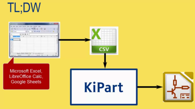
[Dave Vandenbout] a.k.a [xesscorp] has written a couple of utilities for KiCad. When working with large multi pin parts such as micro-controllers, creating a schematic symbol from scratch using the traditional KiCad schematic library editor can be quite tedious. KiPart is a python script that uses a CSV table as its input to generate the KiCad schematic symbol and is able to create multi-part symbols too. Usage is quite simple. The csv file needs a part name on its first row. The next row contains the headers. ‘Pin’ number and Pin ‘Name’ are the minimum required. Additionally, you can add in ‘Unit’, ‘Side’, ‘Type’, and ‘Style’. Unit is used when defining multi-unit parts. Side decides the location of the pin, Type its function, and Style is its graphic representation. Running the KiPart python script then results in a nice KiCad schematic symbol. Besides, KiPart can specifically generate schematic symbols for the Xilinx 7-Series FPGAs and the Cypress PSoC5LP. There are a whole host of options to customize the final output, for example ordering pin placement based on pin number, or pin name or pin function. Source files can be obtained from the [xesscorp] Github repository.
KiCost
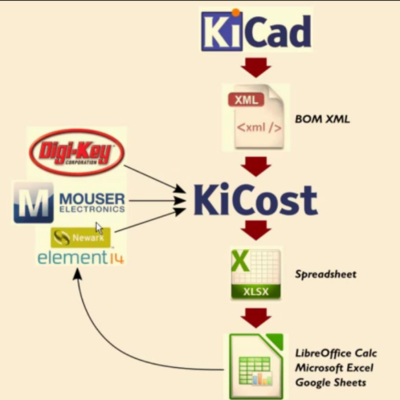 Another useful utility from [xesscorp] is KiCost. It is intended to be run as a script for generating part-cost spreadsheets for circuit boards developed with KiCad. The one piece of information you need to add to your schematic parts is a manufacturers part number. The KiCost Python script then processes the BOM XML file, reading the manufacturer part number, scraping the web sites of several popular distributors for price and inventory data, and creating a costing spreadsheet. You can grab the source files from the KiCost Github repository.
Check the two videos below where [Dave] walks through the two utilities.
Thanks to [RoGeorge] for sending in this tip by commenting on the Open Source FPGA Pi Hat built by [Dave] that we featured recently.


Parts management for KiCad – and all PCB CAD software – is stuck in the 1980s. Parts and footprints should be kept in relational databases, searchable by part number, footprint, manufacturer, function, and/or a variety of other attributes. Better yet, that database should be online, with manufacturers and individuals able to contribute new parts that become immediately available to everyone.
Hell yes. I totally agree.
I agree completely. And it would be super sweet if there was a standard for these part models so any of the low cost or open source schematic capture programs could use them.
Did you ever try the newest version of KiCAD? There is an online library of components already. You can see yourself: http://kicad-pcb.org/
PS: Anyway KiCAD is much better than the foolish Eagle sh*tware… :)
Martin, “Did you ever try the newest version of KiCAD?”: I haven’t, but I plan to. I used to use KiCad, then switched to DipTrace in hopes of finding better parts management. I’m finishing up a DipTrace-based project, but I think for my next project, I’ll try KiCad 4.x.
FWIW, I can’t find any documentation on how to use the KiCAD online library you reference. Some googling yields a dozen links, several strongholds of libraries of various states :\
https://github.com/KiCad/kicad-library As far as I can tell, this git repository is the library. You would just have to sync every time there is an update to use it with all the latest versions.
You have to be careful not to break your designs doing this though…
For instance someone got the idea to make the small resistor smaller which is cool, a good idea,… but it became disconnected in all my circuit schematics. The problem is that kicad symbol connections are not tied to a numbered node on a symbol or even a pin name they are tied to it’s location in the schematic.
I usually just keep a library of my own parts for a lot of things that must work… that I want to use like switches and fuses because kicad doesn’t have them and I don’t have 3d models for them. That said I use kicad’s built in SMD footprints in 95% of my uses.
Also there is no guarantee the kicad libraries are tested … I made a footprint for a FA-238 crystal for instance and it worked fine in 80% of the boards I made but 20% of them failed due to insufficient soldermask I believe and the solder shorting out some of the chips. Basically just enough for the DRC not to care but bad enough that it was failure prone.
There is, is called Designspark, check it out http://www.rs-online.com/designspark/electronics/eng/page/mechanical although not open source, it does have an online database, where you can search components by name, part #, function, etc, (pars from RS and Allied Electronics) they provide you with a free 3d cad design software, and is all embedded in there, no need to convert files and etc etc, you can make a B. O. M right there in the 3 d model of your pcb or mechanical part, search for availability and all that, so you have pretty much all you need in one software, you can design and track everything you need on a project, except circuit simulation, but I think they have a pro version for that, I personally use multisim for circuit simulation
Yeah, like I would like to get footprints and symbols from every honk and donk on the planet who naturally all know how I need them, what specs they need to obey and whatnot..
It takes more time to check someone else’s work and remedy/modify it compared to do it yourself right the first time how you need/want it if the tools are geared for it.
“It takes more time to check someone else’s work and remedy/modify it compared to do it yourself right the first time”: Of course, you’re assuming that someone else doesn’t do it right, but that you always do it right. ;-)
When I enter the parts myself, at least they are all consistent, with similar pin arrangements, and drawing style. When you import parts from various sources, you’re guaranteed to end up with a mix of styles which encourages errors later on. Also, some parts are just wrong. A common mistake in Eagle libraries is to have an automatic solder paste shape, equal to the pad. For many components this results in too much paste.
which is of course how some people want it, then doing a % paste mask reduction after layout to fit stencil thickness and a process they know works
I see it the other way: Common mistake is some strange predefined paste mask, often way too small, when you do % reduction from the pads except with some odd components. But I also have already seen “wrong” numbering in some example libraries even from major E-CAD Tools. Like SOT-23 parts having the single pin NOT number 3. It was consistent with their schematic symbols, but not reusable when you draw parts with numbering according to the datasheet and sometimes a dangerous trap if you did not notice it, leaving to unusable PCBs.
It is also depending on your planned PCB (minimum line spacing and layers).
But at least schematic symbols can often be used from a OS library.
Absolutely. CircuitMaker and Altium seem to pull from a curated database, which makes it fast and easy. But then, that’s why Altium costs so much.
Sparkfun is probably the most progressive in this game, with their github libraries that they maintain.
I believe that part of the problem is the absolute mess of format standards that exist out there for parts information. There *should* just be a simple JSON based high level description language, that lets ones specify a part, and then generate any other format from that. Some existing formats *probably* fill exactly this role, already, though.
Still, if something entirely GPL and vendor neutral like that existed, then chip manufacturers could be invited to contribute their exact footprints as dimensioned in the part datasheets, and provide some schematic blocks.
Lastly, it is kind of shocking that there is not a rational Eagle library manager, or at least one that I have found. It’s all just XML! Python XML parsers exist, and all someone would have to do is wrap a web/in-the-browser interface (since that is the way that everything is done now) around some code that loads and deals with all the relational mumbo jumbo.
It would be nice if the manufacturers would standardize on a part footprint terminology. The old JEDEC one isn’t good enough to cover all the new packages, each with their own variations. ONE standard footprint system (IPC?) which would uniquely define the required footprint and eliminate the entry of all those dimensions.
This is why i quit kicad.. Don’t like to live in the 90’s
Is this a response to my comment that parts management is stuck in the 80s? If so, let me clear: I haven’t found any CAD program that isn’t. Eagle, DipTrace, and Altium also have atrocious parts management. I haven’t played with the new online CAD software much, but my impression is that their part catalogs are also very primitive.
If you’ve found a CAD package that has good parts management (i.e. not flat file libraries), I’d love to hear about it.
I work with Altium. There is no comparison with Kicad.
Yes there is. Altium cost 4000-5000€ per year and KiCad is free and open source. There’s your difference.
Luis, perhaps you could describe parts management with Altium. I’ve never used it, but I got a demo from Altium at a trade show and its ability to search through its parts database looked very limited – more like a flat file than a relational database. For example, let’s say you want to use a new PIC32 microcontroller in a QFP64 package. It’s not in the library, but you can easily make it by tweaking an older PIC32 QFP64. How would you find such a part in the existing library? Once you created the new part, where would you save it? In a file in a directory you’ve created? If so, how would you share your design with other people who don’t have that file? Once Altium sends out a library update that includes the part you created, how would you manage the fact that you have two copies of the same part?
As a hobbyist, I’ll never spring the cash to buy Altium. But I’d really like to know if someone – anyone – has addressed these problems.
You have Altium Vault with every IC available. If it not exists, you can design one with a awesome wizard in less than 1 minute, more two minutes to name the pins (altium have another tool for extreme fast pin naming).
You can join the component schematic and footprint as you like, one time only. you don’t need to join every time as you do in every project with kicad. You can join multiple footprints for a single component schematic etc..
For everything you need to do on altium, you have a tool or wizard that do everyting for you.
oh, and more. You can save the libraries two diferent shapes, Schematic and footprint separately or integrated. You can send this file to a person, they can click on a update button and every component on his project gets updates with the most recent component design.
Luis, some of that sounds nice, but I don’t think it’s getting to the crux of my issues. How do you find a PIC32/QFP64 part? Is there a single search on those two terms, or are you browsing through a (sub-)list of components? When you create a part, where does it go? Do you need to choose a file name that it gets stored in? If so, that’s bad. Once you’ve created a new PIC32 part, does it show up in a list of all PIC32 parts (yours plus Altium’s) or do you need to look in two different places (Altium’s library and your library)?
BTW, as you know, Altium Vault is a separate purchase from Altium Designer – and they’re both very expensive. Your comment about quitting KiCad because you don’t like to live in the 90’s was a little snarky. Your ability to spend many thousands of dollars on a CAD tool (or have your employer spend it on your behalf) was a big part of your ability to quit KiCad.
I think Luis owes all of us a round of altium licenses, although i’ll pass. I’ll stick with kicad for my needs.
JFYI Luis, you can link the schematic symbol and a footprint in KiCAD also once, not every time you do a pcb (but you’re free to do so if you wish). That feat is available for at least a year now.
Cadence uses MsSQL databases in their CIS versions. Worked with it, and miss it now that I work with the db- less version
Altium isnt thaaat bad!
I use OrCAD at work, and I have a similar gripe. We have had to develop our own processes to manage our parts libraries with out-of-tool spreadsheets. One benefit is that we have a relatively small database of components.
I have heard that the CIS add-on adds a parts database management system. My understanding is that it is geared towards production shops for managing parts. We don’t use it, largely because we’re an R&D shop and do not feel it necessary to pay more for the CIS stuff which is not geared toward our main product (technology R&D).
We also use orcad where I work. Before I used Altium and Eagle for my hobby or university projects ( with over 10 years of experience)
Orcad (16.3 or .6) is a huge stepback for me. Overcomplicated buggy piece of cr*p, with minimal ergonomics.
The SAP integration is the cherry on the top.
Okay, the Allegro layout editor has some nice features but arghhh….
Some idiot on the management bought this software who never made a single PCB. Also when they search for new collegues everyone has only Eagle or Altium experience also now. Lol.
even for a small shop CIS has value, when drawing a schematic and need part of roughly this value or this function you browse through the part database and can see ok I got 2000 of this part in stock so lets pick that one instead of the one there is only 10 left of
I’m seeing a demand here. It wouldn’t be the hardest thing ever open-sourced and released for everyone to use.
As an example: https://github.com/FreeCAD/FreeCAD-library
No part library ever has every part you need; there’s always a couple of parts you need to build yourself. Making that quick, easy and accurate is extremely useful.
“Making that quick, easy and accurate is extremely useful”: Natch, but that’s not what bothers me most. When I make a part, I want it fully integrated into the library – not in a separate file that forces it to be in a separate category too (e.g. the PIC32 you created is not listed next to all the PIC32s in the built-in library). I want it easily distributed (e.g. I don’t have to figure out what library files to send to someone when I send him my design). I want the recipient to be able to easily integrate it with his library (he doesn’t have to worry about duplicate parts, or my library organization being different from his). When the CAD software manufacturer releases a new library that has an official version of the part I created, I want to be able to resolve the differences.
don’t most of the tools make a cached library for the parts used in a project?, you don’t want all you old designs to suddenly be broken because you changed parts of your global library
Eagle actually handles all of that pretty well, except for integration of parts from different libraries into one (requires going through the much-reviled part creation process). New variants can live right along side the original parts. Updating parts in a design is easy. And board/schematic files contain embedded instances of every part used. There’s a supplied program you can run to create a library of all the parts used in someone else’s design (exp-project-lbr.ulp); this is handy for recovering esoteric parts like tube sockets etc.
Does KiCad provide a way to recover parts from existing designs?
Yes, every KiCAD project has a local symbol and footprint lib (one each) in that very same folder.
If you want to share a project, just hit the zip button and send the package off for somebody else to have a look at.
If you need a symbol or footprint from a project, just load the lib into the relevant editors and copy/move(*) them into your local libs.
*) that part is still clumsy, but they’ll be working on it sometime in the future.
I’m not entirely sure those people know how Github works..
“If you are interested in contributing to this library, please ask for write access to this repository on this FreeCAD forum thread: http://forum.freecadweb.org/viewtopic.php?f=19&t=4205”
What’s wrong with pull requests?
All your comments seems to be completely unrelated to how the software manufaturers are dealing the parts. the real question is how is it possible that in the electronics domain, no standard exists for footprints and other datas related to the components and uses by those softwares, I would expect all those datas to be available in centralized websites like RS or mouser or others. Lack of standards is the real point, there should be no way to allow those kind of softwares to deal with proprietary file formats that lock your develeopement to one product. (in my own opinion, this is why everybody should gather behind kikad, since behind all the drawbacks, this is an open source solution that doesnt lock your desings behind a licenced file format.
Absolutely! It would be nice to have standards for component libraries and even the design files. Unfortunately, I expect this never to happen. I can’t think of any commercial software – word processors, image editors, etc. – that use a standard format for their native files.
Using KiCad isn’t really a solution to that. Sure, their file formats are open, but since no one else uses them (not even other open source CAD programs) you’re still locked in.
It starts with the real world footprints themselves.. take any package and you’ll find at least three different footprints and package dimensions for any two manufacturers :-)
At least the file formats are open, human readable and documented – so they can be converted.
IPCC
The standard is for manufacturing processes.
What is amazing is that there are so many crappy proprietary CAD tools out there. This is a perfect opportunity for an open source tool with an open source library to dominate, yet they don’t.
I think this is where Altium’s Circuit Maker slightly wins. It has a built in tool to search for parts and a lot of symbols and footprints already there. Unfortunately, I don’t like Circuit Makers UI and struggle to get on with it.
A bit of snooping around, Circuit Maker uses Octopart for all their BoM integration and SnapEDA for symbols and footprints. I have only had a quick look at the both of them, but they look useful.
Octopart has an online BoM tool which looks quite good, searching many manufacturers and giving batch costs. Looks like they provide an API too, so a KiCAD plugin on the horizon perhaps?
SnapEDA gives confidence ratings for parts, and you can download (for free) parts for Altium, EAGLE, Cadence, OrCAD and KiCAD. (Plus two other tools I’ve never heard of…). A SnapEDA plugin to KiCAD would be awesome, though no sign of an API on their website. Guessing there must be a way if Circuit Maker has managed it. Nevertheless, quick easy access to a lot of symbols and footprints is much better than drawing them out! It also looks like they have some reference designs for parts and some forums, though no idea how good they are.
Hi! Natasha from SnapEDA here. Really great ideas on this thread, and I’m glad this topic is getting the attention it deserves. We actually do have an API. If you email me (natasha@snapeda.com), I can share more about it. One of the most unique things about SnapEDA is that we’re bringing transparency into the quality of CAD files. We have a ‘diagnostic checker’ that runs algorithms through each CAD file to check for common manufacturing issues such as misplaced centroids or sllkscreen overlapping copper. If you click “Validations” on any page you’ll get an idea of what we’re aiming to achieve. Of course, we’re very open to hearing which quality checks we should be adding next, so please keep the feedback coming. :-) We’ll also be publishing our internal component creation standards soon too for the community to adopt if they so choose.
I always use C. Rohrbachers KiCad quick library generator: http://kicad.rohrbacher.net/quicklib.php . Its quite similar to KiPart, but is available online (it also has some more options and it gives you a preview of the generated part).
All the complaints and CAD wars aside, this may be one of the most useful things I have ever seen on HaD and I’ll be trying it our tomorrow. Beats the hell out of the time I wasted on the Media Lab buzzword talk a few posts back. Coffee in one hand, word salad exchanges between academic dweebs! Truly awful. And the enbiggenousnous! When you don’t have the ability to describe the fit between a person and a job you say it is their “impedance match”, and in one swell foop show how incredibly clever you are and degrade the word “impudence” as used in electronics. Same for DNA. A very specific substance whose name is abused for a Burning Man (are you kidding?) rave. These uber-smartnessers really should be able to come up with a term for data sharing. There was enough of this vocal trash to make my ears bleed. At least I don’t think anyone used the meaningless “granularity” to describe fineness of a mesh or ADC or time resolution, etc. Thank Jeebus there were no man-buns!
But I wander, and to make a point. +10 on this. Great idea, well executed, real-world application widely usable. Yes, I want a button or menu item in KiCAD to invoke this instead of the command line, but the code is all there and nothing is stopping anyone. (Or I want Altium to exchange for the Protel seat I bought in 1998 and maintained for years till they abandoned us).
Great job and videos Dave, and nice find Anool for a HaD writeup!
Thanks! Let me know if you encounter any problems. I’m fixing things as they arise.
One thing I did on Windows is I added KiCost to the context menu for XML files. Now I can right-click on the BOM XML file for a project and initiate KiCost without opening a command window. Let me know if you’re on Windows and don’t already know how to do that. (I could probably do something similar for KiPart except it has more options that users want to adjust.)
You could also add KiCost to eeschema as a BOM plugin. The problem I saw with that was that it would get initiated whenever you generated a BOM. Since KiCost has to query the distributor websites for part data, I thought the delays for doing that were too much to use that route.
Impudence isn’t an electronics word? However, the concept of impedance matching does have a strong parallel in person-job matching. I am totally OK with such uses… its field specific and the concepts are similar. What I find annoying is words that share the same sound or spelling with meaning changing only by context. I.E minute and minute….. see what I mean.