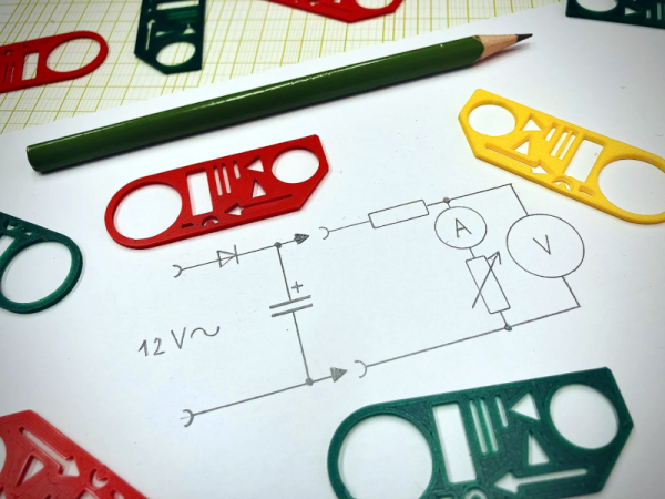
If you want to draw schematics today, you probably sit down at your computer. Why not? There are a ton of programs made to do the work easily, and the results look great. Back in the day, you might sit at a drafting table with a full set of T-squares, triangles, and maybe a Leroy. But what about when inspiration struck at the coffee shop (no, not a Starbucks in those days)? Well, you probably had a schematic drawing template. We were surprised you can still buy these at high prices. Or you can 3D print your own, thanks to [Jan Stech].
Templates of all kinds used to be very common. There were several for schematics, logic symbols, furniture, and even geometric shapes and curves. They were almost always green and transparent. A quick search on Amazon for “drafting template” shows you can still get the generic templates, but schematic ones are still expensive.
We’d wager that, if you’re reading Hackaday, you’ve looked at more than a few circuit diagrams in your day. Maybe you’ve even converted a few of them over to a PCB. It’s a workflow that, at this point, is well-understood. But as designs become more complex, the schematics are harder to create and maintain. That’s why Atopile wants to treat hardware design more like writing code.
We can see some real benefits to this but also some possible drawbacks. On the plus side, reusing chunks of PCB description should be easy. On the other hand, detecting certain errors on a schematic or PCB layout is easier than spotting them in code. Of course, there are probably types of errors that are easier to catch in code, too, so maybe that’s not a problem. Certainly, if you can spit out a schematic from your code, you could — potentially — have the best of both worlds.
If you’re like us, there’s a creeping feeling that comes over you when you’re placing an order for parts for your latest project: Don’t I already have most of this stuff? With the well-stocked junk bins most of us sport and the stacks of defunct electronics that are almost always within arm’s length, chances are pretty good you do. And yet, we always seem to just click the button and place a new order anyway; it’s just easier.
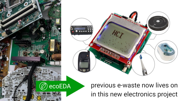
But what if mining the treasure in your junk bin was easier? If you knew right at design time that you had something in your stash you could slot into your build, that would be something, right? That’s the idea behind ecoEDA, a Python-based KiCAD plugin by [Jasmine Lu], [Beza Desta], and [Joyce Passananti]. The tool integrates right into the schematic editor of KiCAD and makes suggestions for substitutions as you work. The substitutions are based on a custom library of components you have on hand, either from salvaged gear or from previous projects. The plug-in can make pin-for-pin substitutions, suggest replacements with similar specs but different pinouts, or even build up the equivalent of an integrated circuit from available discrete components. The video below gives an overview of the tool and how it integrates into the design workflow; there’s also a paper (PDF) with much more detail.
This seems like an absolutely fantastic idea. Granted, developing the library of parts inside all the stuff in a typical junk bin is likely the biggest barrier to entry for something like this, and may be too daunting for some of us. But there’s gold in all that junk, both literally and figuratively, and putting it to use instead of dumping it in a landfill just makes good financial and environmental sense. We’re already awash in e-waste, and anything we can do to make that even just a little bit better is probably worth a little extra effort. Continue reading “EcoEDA Integrates Your Junk Bin Into Your Designs”→
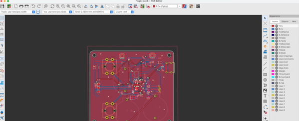
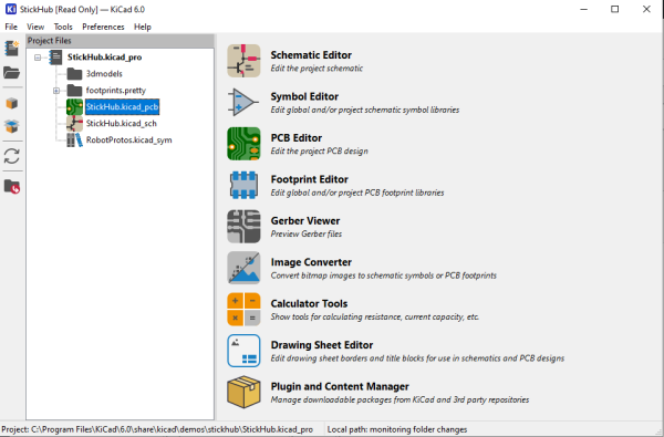
I’ve been following the development of KiCAD for a number of years now, and using it as my main electronics CAD package daily for a the last six years or thereabouts, so the release of KiCAD 6.0 is quite exciting to an electronics nerd like me. The release date had been pushed out a bit, as this is such a huge update, and has taken a little longer than anticipated. But, it was finally tagged and pushed out to distribution on Christmas day, with some much deserved fanfare in the usual places.
So now is a good time to look at which features are new in KiCAD 6.0 — actually 6.0.1 is the current release at time of writing due to some bugfixes — and which features originally planned for 6.0 are now being postponed to the 7.0 roadmap and beyond. Continue reading “KiCAD 6.0: What Made It And What Didn’t”→
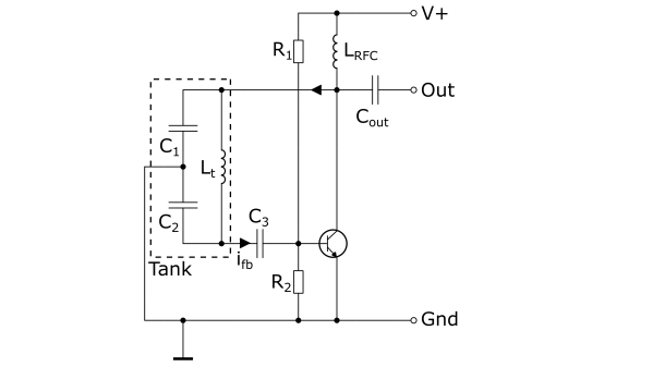
A while back, [Heavydeck] remembered stumbling across the worst CAD package ever, which is a schematic editor whose existence was purely intended for use to make quick circuit sketches for documentation, presentations and the like. All good. But, being based on low quality JPEG graphics, which when blown up to projector size on a big screen, they look really rough. After deciding that the original nasty, clunky interface was just nasty and clunky enough, [Heavydeck] then proceeded to reimplement the idea over the course of an afternoon, and came up with Kludge (possibly the second worst CAD package ever) making an actually useful tool even more useful.
You see, whether you make website content, YouTube tutorials, or just need to write technical reports, if you’re in the electronics business, you’re going to need to make high-quality editable schematic images at some point, and Kludge might well solve some problems for you. Kludge lets you do so many things; you can save a schematic, you can load a schematic, you can even export it to an SVG file. Actually, that’s all you can do, but it is actually just enough. Once you’ve got an image as an SVG, you can whack that into Inkscape to add some more details and you’re done. We demonstrate this with the image above, which was not annoying at all to create.
So here’s to Kludging your way around a problem, and hoping that the somewhat limited symbol library may expand a little more in the future!
When it comes to electronic design, breadboarding a circuit is the fun part — the creative juices flow, parts come and go, jumpers build into a tangled mess, but it’s all worth it when the circuit finally comes to life. Then comes the “What have I done?” phase, where you’ve got to backtrack through the circuit to document exactly how you built it. If only there was a better way.
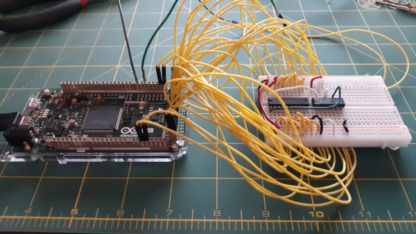
Thanks to [Nick Bild], there is, in the form of the “Schematic-o-matic”, which aims to automate the breadboard documentation process. The trick is using a breadboard where each bus bar is connected to an IO pin on an Arduino Due. A program runs through each point on the breadboard, running a continuity test to see if there’s a jumper connecting them. A Python program then uses the connection list, along with some basic information about where components are plugged into the board, to generate a KiCad schematic.
[Nick] admits the schematics are crude at this point, and that it’s a bit inconvenient to remove some components, like ICs, from the breadboard first to prevent false readings. But this seems like one of those things where getting 80% of the work done automatically and worrying about the rest later is a big win. Plus, we can see a path forward to automatic IC probing, and even measurement of passive components too. But even as it is, it’s a great tool.
If you’ve ever pushed the needle a bit on your Raspberry Pi, there’s a good chance you’ve been visited by the dreaded lightning bolt icon. When it pops up on the corner of the screen, it’s a warning that the input voltage is dipping into the danger zone. If you see this symbol often, the usual recommendation is to get a higher capacity power supply. But experienced Pi wranglers will know that the board can still be skittish.
Sick of seeing this icon during his MAME sessions, [Majenko] decided to attack the problem directly by taking a close look at the power supply circuitry of the Pi 4. While the official schematics for everyone’s favorite single-board computer are unfortunately incomplete, he was still able to identify a few components that struck him as a bit odd. While we wouldn’t necessarily recommend you rush out and make these same modifications to your own board, the early results are certainly promising.
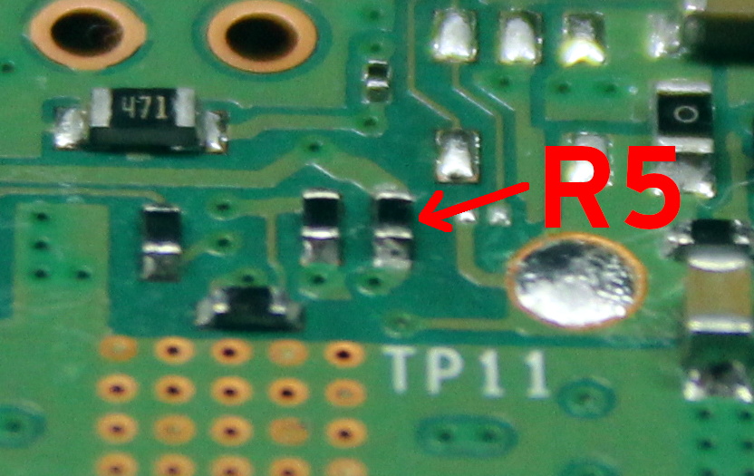
The first potential culprit [Majenko] found was a 10 ohm resistor on the 5 V line. He figured this part alone would have a greater impact on the system voltage than a dodgy USB cable would. The components aren’t labeled on the Pi’s PCB, but with a little poking of the multimeter he was able to track down the 0402 component and replace it with a tiny piece of wire. He powered up the Pi and ran a few games to test the fix, and while he definitely got fewer low-voltage warnings, there was still the occasional brownout.
Do we really need this part?
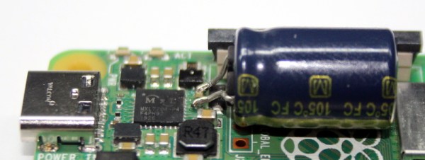
Going back to the schematic, he noticed there was a 10 uF capacitor on the same line as the resistor. What if he bumped that up a bit? The USB specifications say that’s the maximum capacitive load for a downstream device, but he reasoned that’s really only a problem for people trying to power the Pi from their computer’s USB port.
Tacking a 470 uF electrolytic capacitor to the existing SMD part might look a little funny, but after the installation, [Majenko] reports there hasn’t been a single low-voltage warning. He wonders if the addition of the larger capacitor might make removing the resistor unnecessary, but since he doesn’t want to mess with a good thing, that determination will be left as an exercise for the reader.