Measuring the body’s electrical signals is a neat trick… if you can get your equipment dialed in enough to establish dependable measurements. The technique is called Surface ElectroMyography (SEMG) though you’ll hear many call this ECG. They’re essentially the same technology; the Electro CardioGraph instruments monitor the activity of the heart while SEMG Instruments monitor electrical signals used to control other muscles. Both types of hardware amount to an instrumentation type amplifier and some form of I/O or display.
This topic has been in my back pocket for many months now. Back in May we Hackaday’ites descended on New York City for the Disrupt NY Hackathon event. We arrived a day or so early so that we might better peruse the Korean BBQ joints and check out the other electronics that NY has to offer. On Saturday we gathered around, each shouting out the size of his or her t-shirt preference as we covered up our black Hackaday logo tees with maroon maroon ones (sporting the Hackaday logo of course) for a 24-hour craze of hardware hacking.


There were two individuals at our tables who were both hacking away on hardware to measure the electrical field produced by the body’s muscles in some form or another. The electrical signals measured from the skin are small, and need careful consideration to measure the signal despite the noise. This is a fun experiment that lets you work with both Instrumentation Amplifiers and OpAmps to achieve a usable signal from the movement of your body.
At the Hackathon, Andrew Ippoliti had a little amplifier and a microcontroller and was playing with controlling a small motor. He had the analog working fairly early in the evening allowing him time to tweak the motor control into the night until falling asleep with his head on the table somewhere around 2AM.


David Nghiem, who won one of the awards presented at the Hackathon, was seen walking around with his SEMG module semi-permanently attached in hopes of future assimilation. David has an excellent Hackaday.io project with description of how his SEMG project works.
I threw together the following circuit during the summer to see what I could do in my own lab. Let’s take a look.
The Amplifier Board
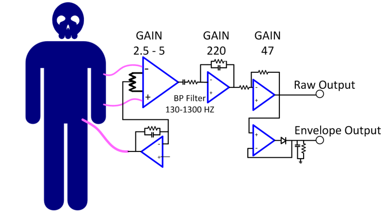
In the block diagram above, three connections are used to pick up the small electrical signature of the body’s muscles. Two leads are connected directly to the inputs of an instrumentation amplifier. You’ll remember from my previous video, Instrumentation amplifiers are special because of their high impedance and low noise characteristics. Often it is not the highest gain block in a chain, its primary job is to dig the signal out from the environment and give it its initial amplification and buffering so that following stages can further amplify a clean signal easily. The instrumentation amp is also good at stripping out a signal, whether noise or just an offset (the common mode part), and amplifying only the difference (the differential). That is exactly what’s going on here.
Since the human body is a great collector of 60 Hz noise (you can touch the tip of a scope probe for an example of how much) the rejection of the 60 Hz common mode is essential. The circuit shown has a feedback path that attempts to offset the effects of low frequency noise by inverting some of the signal, low passing it and feeding it back to the body.
Finally I added a jumper selectable filter which is essentially a half wave rectifier (remember the post on including the diode in the feedback loop to make it a zero forward voltage diode?) and a capacitor with discharge resistor. A small positive pulse causes a fairly immediate positive voltage on the capacitor and then the resistor causes a slower discharge making the circuit into a pulse stretcher.


From here it’s a simple RC high pass filter and then a low pass filter and amplification stage followed by another amplification stage, standard Op Amp stuff.
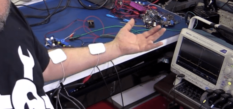
 As it turns out the circuit was able to produce a signal of roughly 5Volts by squeezing my hand. Just to help visualize that it really is working and not just displaying noise I connected up an LM3914 bar graph driver and was able to get a full scale display by flexing my arm muscles.
Safety
The biggest change I would make to the circuit would be to add 100k resistors in series with the leads as sticking anything to the skin that isn’t current limited can be dangerous, especially if there is AC operated equipment that has an issue such as a floating ground. In this case I used a 9V battery to power the circuit to eliminate the need for the extra components while shooting the video.
With just a handful of chips and we can see a little bit about what is going on under the skin. Sometimes these simple things still amaze me. I hope you feel the same way. I’d love to hear about your own SEMG projects, and any ideas you have for using this technique in future videos. Let me know in the comments below.


I have to make this in the second year of my study,
already excited!
I built a similar controller for an animatronic tail back in 2003:
http://wolftronix.com/biotail/biotail.htm
You could wag the tail by flexing your leg muscles.
The bias for U1A isn’t quite correct.
The AD620 runs the gain setting resistor (RG+ and RG-) about one Vbe drop below it’s inputs. So a simplistic scheme to center the RLD should set the bias to be Vcc/2 – Vbe.
This is ignoring the fact that the AD620 is neither rail to rail on its input or output. That makes it more complicated. Which is left as an exercise for the reader.
The RLD has another issue too, I ended up just using ground for the purposes of SEMG.
I’m not convinced that’s such a good idea.
353’s (image of board) also don’t work so well on a single +5V power supply. Could that be a problem?
I should have put a buffer between the inverter and the tap on the 623, I don’t like the cap being visible to the instrumentation amp. It was a slap together design awhile back where I shot a PCB instead of breadboarding it. When I went to shoot the video I was out of stock on the amps I planned on and dropped in what I had. The output pegs 5V when I wiggle my arm so something is working correctly for purposes of recreating what we were playing with that night at the Hackathon.
I also don’t think that the Right Leg Drive (RLD) needs to be that accurate, it mostly is trying to unload the common mode voltage I think. I would think that a larger error would be the phase shift cause by the low pass function/filter… of course there are ways to correct for that also if critical.
Hackaday writers should stop Korean BBQ. They need to stay fit in case they get abducted by Aperture Labs and get surrounded with moving levels full of turrets and tricks.
As long as they avoid the cake, they’ll be fine… then again, I heard it taste quite fine. :-P
You mention adding a series resistor on the lead inputs, but to be safer you’d want to have dual series resistors due to possible SPOF removing the safety from the system. All medical devices like this should cater for any single failure not injecting too much current into a person.
That’s an excellent example of the kind of paranoia needed to design life safety stuff. Assuming that the resistor can fail shorted, which is rare but could happen and that there is a danger condition already in effect that puts it in a dual fault condition, yet a second resistor is cheap insurance.
In real life the leads are carbon fiber and safe for MRI and defibrillation while hooked up etc.and have an inherent resistance that is also safer.