Electric cars are all the rage lately, but let’s not forget about the old standby – internal combustion. The modern internal combustion engine is a marvel of engineering. Today’s engines and surrounding systems have better power, greater fuel economy, and lower emissions than anything that has come before. Centuries’ worth of engineering hours have gone into improving every aspect of the engine – with one notable exception. No automotive manufacturer has been able to eliminate the engine’s camshaft in a piston powered-production vehicle. The irony here is that camless engines are relatively easy to build. The average hacker could modify a small four-stroke engine for camless operation in their workshop. While it wouldn’t be a practical device, it would be a great test bed for experimentation and learning.
Suck, Squeeze, Bang, Blow
 A multi-cylinder gasoline engine is a complex dance. Hundreds of parts must move in synchronicity. Valves open and close, injectors mist fuel, spark plugs fire, and pistons move up and down. All follow the four-stroke “Intake, Compression, Combustion, Exhaust” Otto cycle. The camshaft controls much of this by opening and closing the engine’s spring-loaded intake and exhaust valves. Lobes on the shaft press on tappets which then move the valve stems and the valves themselves. The camshaft itself is driven at half the speed of the crankshaft through timing gears, chains, or a belt. Some valve trains are relatively simple – such as overhead cam engines. Others, such as the cam-in-block design, are more complex, with pushrods, rockers, and other parts required to translate the movement of the cam lobe to movement at the valve.
Exactly when, and how fast a valve opens is determined by the profile of the cam lobe. Auto racing and performance enthusiasts often change camshafts to those with more aggressive profiles and different timing offsets depending on the engine’s requirements. Everything comes at a cost though. A camshaft machined for maximum power generally won’t idle well and will make the engine harder to start. Too aggressive a lobe profile can lead to valve float, where the valves never fully seat at high RPM.
Myriad Solutions
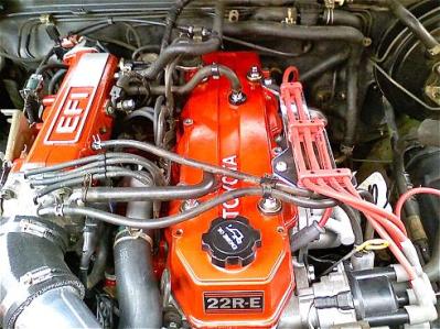
 Engine manufacturers have spent years working around the limitations of the camshaft. The results are myriad proprietary solutions. Honda has VTEC, short for Variable Valve Timing and Lift Electronic Control. Toyota has VVT-i. BMW has VANOS, Ford has VCT. All these systems provide ways to adjust the valve action to some degree. VANOS works by allowing the camshaft to slightly rotate a few degrees relative to its normal timing, similar to moving a tooth or two on the timing chain. While these systems do work, they tend to be mechanically complex, and expensive to repair.
The simple solution would be to go with a camless engine. This would mean eliminating the camshaft, timing belt, and most of the associated hardware. Solenoids or hydraulic actuators open and close the valves in an infinitely variable number of ways. Valves can even be held open indefinitely, effectively shutting down a cylinder when max power isn’t necessary.
So why aren’t we all driving camless engines? There are a few reasons. The advantages of camless engines to camshaft engines are analogous to the advantages of electronic fuel injection (EFI) vs carburetors. At the core, a fuel injector is a solenoid controlled valve. The fuel pump provides constant pressure. The engine control unit (ECU) fires the injectors at just the right time to inject fuel into the cylinders.The computer also leaves the valves open long enough so that the right amount of fuel is injected for the current throttle position. Electronically this is very similar to what would be required for a camless engine. So what gives?
Hackers in their 30’s and beyond will remember that until the late 1970’s and early 1980’s, the carburetor was king. Companies had been experimenting with EFI since the 1950’s. The system didn’t become mainstream until the stiff pollution laws of the 70’s came into effect. Making a clean, fuel-efficient carbureted engine was possible, but there were so many mechanical and electronic actuators required that the EFI was a better alternative. So the laws of the 70’s effectively regulated carburetors out of existence. We’re looking at much the same thing with camless engines. What’s missing are the regulations to force the issue.
All the big manufacturers have experimented with the camless concept. The best effort to date has been from Freevalve, a subsidiary of Koenigsegg. They have a prototype engine running in a Saab. LaunchPoint Technologies have uploaded videos showing some impressive actuator designs LaunchPoint is working with voice coils, the same technology which moves the heads in your hard drive.
None of this means that you can’t have a camless engine now – companies like Wärtsilä and Man have engines commercially available. However, these are giant diesel engines used to drive large ships or generate power. Not exactly what you’d want to put in a your subcompact car! For the hacker set, the best way to get your hands on a camless engine today is to hack one yourself.
Ladies and gentlemen, start hack your engines!
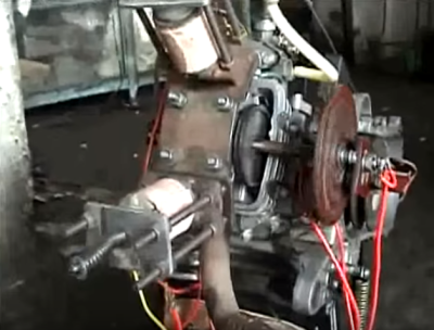 Simple, single-cylinder camless engines are relatively easy to build. Start with a four stroke overhead valve engine from a snowblower, scooter, or the like. Make sure the engine is a non-interference model. This means that it is physically impossible for the valves to crash into the pistons. Add a power source and some solenoids. From there it’s just a matter of creating a control system. Examples are all over the internet. [Sukhjit Singh Banga] built this engine as part of a college project. The control system is a mechanical wheel with electric contacts, similar to a distributor cap and rotor system. [bbaldwin1987’s] Camless Engine Capstone project at West Virginia University uses a microcontroller to operate the solenoids. Note that this project uses two solenoids – one to open and one to close the valve. The engine doesn’t need to rely on a spring for closure. [Brian Miller] also built a camless engine for college, in this case Brigham Young University Idaho Camless Engine. [Brian’s] engine uses hall effect sensors on the original camshaft to fire the solenoids. This route is an excellent stepping stone before making the jump to full electronic control.
It wouldn’t take much work to expand these projects to a multi-cylinder engine. All we’re waiting for is the right hacker to take up the challenge!


All I want is a DFI two-stroke twin engine for my bike. Definitely camless!
You mean your bicycle?
Formula 1 engines are all camless, they use pneumatic valve actuators, so they can turn at up to 20,000 rpm (usually more like 12,000 for fuel efficiency)
The current formula limits engine RPM to 15,000 rpm (section 5.1.3 of the 2016 technical regs). The engines might be capable of 20,000 rpm, but they’ll never hit that in a race because of rules.
Also, they still use cams. It’s pneumatic valve springs not actuators. This is due primarily to section 5.9.2 of the technical regs which prohibit “variable valve timing and variable valve lift profile systems”. There’s no bonus to be had from going to actuated valves if you can’t vary timing/lift.
No, they aren’t and don’t. They use pneumatic valve springs. They have cams like a normal engine. The use of pneumatic valve springs plus a short stroke allows the high engine RPM.
The Fiat Multiaire system – if this is what you are getting at in a round about way – is a consumers nightmare. The system consumes oil and is very unpredictable under certain stress conditions. It’s pure engineering garbage to the customer, and sounds good on paper to the environmentalists. It should be eliminated and outlawed. Or just keep it in Italy.
Interesting article. I suspect that it won’t be long before there are Koenigsegg cars on the road with this technology. However, most of us won’t be able to afford to buy one.
I think that camless engine technology is like any other engine improvement tech: It won’t start showing up on normal passenger cars until there is a decent monetary or regulatory incentive for manufacturers to start producing it.
Right, good enough and cheap will always win out over perfect and expensive unless there is something that makes good enough more expensive.
Electric solenoid valve actuators were in Hot Rod magazine in the 1970s. Never panned out back then. Things are better now. I’ve seen a running engine with a rotary sleeve valve, Turbo of course, and RPM only limited by the crank strength. If you can think it, you can do it..
“I’ve seen a running engine with a rotary sleeve valve”
“Silent Knight” engines from the 1930s used them as did a number of aircraft engines.
The difficulty was (and is) achieving effective seals. That’s why poppet valves are still with us and rotary sleeves are not.
The more modern way of solving valve bounce issues is to move away from poppets to desmodronics, but that adds complexity (on the flipside it reduces friction dramatically. A poppet valvetrain is one of the largest frictional components in any engine.). You might think of these dual-solenoid setups as a kind of electronically actutated desmodronic system.
Pneumatic assisted cams are already in production cars. Fiat have them on the Twin-Air units with some electronic controls to allow things like double valve opening during the compression stroke. The big “thing” is removing the camshaft entirely and I’m sure that Fiat has that in their sights (simplifying the mechanicals saves a lot more money than the small amount of extra electronics required, given the cams in those engines don’t directly operate valves)
WRT keeping the valves open to deactivate cylinders: This was evaluated when various makers started producing 8-6-4 engines in the 1970s and it was found to be more efficient to keep them closed, using the cylinder as an air spring.
8-6-4 engines are still in production..Cad, Chrysler 300 C and others. The rotary I saw run was a Detroit Diesel 2 stroke converted to a four stroke, custom head, with a rotary valve running on a belt, (A bar with a slot in it) turboed, and it screamed. The application was APU for the military. (Shhh)
I never said 8-6-4s weren’t still being made, just that there’s a reason they deactivate the cylinders with the valves closed. :)
I’d be interested in seeing that conversion. Old style rotary sleeve valves were driven from below. Rotary valves embedded in the head have generally had short service lives, which is why they don’t appear in general automotive use.
https://www.youtube.com/watch?v=B0TkP18gZRE&feature=youtu.be#t=56.758662
The internal resistance of driving a camshaft against the heavy valve springs surely saps power right?
What’s the MTBF on a solenoid hammering away hundreds of times / second vs a mechanical cam?
It’s just a coil of wire and a metal piston. It’s hard to think of many failure modes. Broken wire, excessive heat build up, wear from sliding surfaces. Pot the solenoid, over-spec it for the duty cycle, use a low friction liner, perhaps some sort of oil-impregnated piston.
And then your electronics fail and ram your valves into your piston, because non-interference designs are highly inefficient and impractical.
Um… cars already have electronics. It’s not any more or any less reliable to electronically control valve position.
One failure of the firmware or sensor and you have a busted piston/bent valve.
The probablility of failure may be low but the cost of damage is high. I suspect no camless engines exist because the MTBF of a completely mechanical valve timing is higher than a firmware/sensor/solenoid version.
Pretty side I’d trust a well specced solid state solenoid driver over a timing chain or timing belt. One broken link or a few skipped teeth and you have busted piston / bent valve.
And fuel injectors run for years without failure. And they are solenoids.
@Mark: You are correct, however when a fuel injector fails it doesn’t cause immediate, expensive physical damage to an engine. I would love to see a camless engine myself but no system is flawless. If I rev my truck’s custom built 350ci engine too high it floats the valves, and it was designed for towing/hauling, i.e. demanding loads. Every system has its limits.
In a non-interference engine failure would have no ill effect, other than no (or poor) compression in that cylinder.
Except the current electronics will not BLOW or otherwise damage the mechanics when they fail. Having an exhaust valve stuck closed can put way too much pressure on the exhaust cycle (turning it into another compression, but where the starting pressure is much higher than intake ending). That would instantly stall an unloaded engine. Now think a car cruising at 2000rpm, where such a cycle takes 15ms and the car has 1000+kg of inertial mass.
This is another technology I will never trust, just like electronic brakes and steering (not electronically assisted….fully eletronic). You may think SW is simple, but you can do so many things (good or unintentionally bad) that you just don’t have enough time to learn everything like in mechanics and hydraulics. If anybody tells you they figured all the ways a SW can fail, it means the SW is pretty simple.
PS: I work on transmission control units and I’m telling you we have all kinds of safeguards which disable the electronic control to fall back on mechanical means to disconnect the gearbox….it’s called damage control… And those are still not infailable.
Sort of like saying “mechanical pencil lead and wood pencile lead are equally strong, since they are both lead and used for writing.” Clearly not. Lots of physical reasons for this not being true.
Fuel injects are solenoids, and valve lifters can be mad of solenoids, so their MTBF ought to be the same.. NO.
First consider scale. The fuel injector valve is VERY small. The mechanical stopper itself is possibly half a mm. The solenoid coil is smaller than a pea. The total weight to move is measured in mg. The only real work being done is against the fuel pressure. The stroke of the solenoid is fractions of a mm. Activation current is really low.
Now the valve lifter: CM stroke length. Large valve surfaces against pressurized gas explosions. Work against springs. The whole mechanism is MUCH larger. Factor of 10 at least. Big activation currents. Bigger inductive kick. High frequency operation will cause a lot of high current spikes. Power supply has to be much more substantial than for EFI.
Back to the fuel injector: fuel itself is the cleaner, lubricant and coolant. Now… The valve lifter: needs some custom design work to keep it clean, lubricated and cool.
Urp ok after looking at cutaways online, fuel injectors are not THAT small.. But still much smaller than what would be needed for a valve lifter.
Pneumatic or hydraulic activated valves would be the way to go.
The cam belt in cars that don’t have cam chains is less reliable than the electronics by a large amount. In my Subaru it’s actually considered a wear item to be replaced every 100,000 miles. I’d much rather have a set of properly designed solenoids where the failure mode would most likely be to fail with the valve in the closed position. It seems that the engine would be much less likely to crash the valve train and self destruct that way.
I’ve cursed the Volvo engineers that worked on the T6 in my wife’s S80. Who in their right mind makes an intrusive valve system using a Kevlar belt? We’ve gone through 4. One time two valves took a hit and the local machine shop added a new wing to their shop.
I’ve had a couple of occasions where I had to “reboot” my 2002 truck in order to get the engine control unit to work properly. I would start driving, but it would be running extremely rough. I’d pull over, shut down the truck, start it back up, and all was well.
If the ECU had been in control of those valves, and if it was mechanically possible for the valves to be struck by the pistons, I would have had very expensive engine damage. Instead, I had 30 seconds of inconvenience. Unless the timing belt starts jumping around, cam systems generally fail safe.
That old ECU may not have had the best fail-safe redundancy circuits in it, but electronic valve control crosses a different line entirely.
The solenoid probably fails closed. The drive transistor probably fails short (open valve). So you would need a VERY fast secondary safety shut off. But of course, the reliability of a timing belt is also limited.
Well, there are many cars with belts instead of chains. Actually chains are becoming a bit unusual. And failure in closed position during exhaust cycle would blow your engine up aswell, because you have all the expanded gas produced by the combustion which is a lot more than the unburned air-fuel mixture. And then your poston moves upwards, trying to push all that stuff out. But the exhaust valve is closed, leading to massive compression, blown rings, massive amounts of blowby, blown headgasket etc.
My turbo Subaru engine would likely grenade itself if the exhaust valves were stuck closed. I’d imagine you’d see some rod-bearing–destroying detonation in there if the air/heat couldn’t escape before the next compression cycle.
I also find the 10-year / 100,000-mile timing belt replacement to be fairly reasonable. It only takes a few hours to do, only happens once a decade, and presents a good opportunity to replace the oil and water pumps, etc., while you’re in there :-) Of course, I’ve also had an engine with a timing chain destroy itself too (with the chain wearing the tensioners, coming loose, then slapping the water pump.)
I’m not sure a piston / valve crash with a camless would be as bad as a cammed engine. With a cammed setup, you have two metal objects smacking into each other, with nowhere else to go. On a camless, the piston would hit the valve and be pressing against the force of the actuator. I’m not saying that no damage would be done, but it might not be as bad as the bent stems and cracked crowns we’re used to seeing.
All this said – a properly designed camless setup would fail safe – so no damage could be done.
You are counting on the piston and valve colliding head-on…
It’s not that there is nowhere to go, it’s that the valve is usually on an angle and will get bent if the solenoid holds it open too long… resulting in the edge of the valve usually punching right through the flat of the piston.
Regardless, I don’t think it’s some flaky thing that will fail often… it’s pretty rare for a solenoid to fail in the ‘open’ state, and for those of us concerned of ‘firmware’ glitches physically breaking the engine… mayhap you should look into the ECU of most cars… I’ve got a ’93 and the ECU still operates flawlessly.
Doh! You’re right, I was thinking two dimensionally. Valves are rarely parallel to the crown. I still trust that a well designed system will work. Same way I trust my electronic brakes to work. So far they’ve been good to me.
Most recommended timing system replacement periods is 100-120k belt or chain makes little difference
Timing chain/belts breakage is not that uncommon. Also, I don’t think interference engines are that common.
modern engines are interference, because the ‘headroom’ between valves and the pistons were axed in the name of efficiency.
[Hoso] is right, most modern automobile engines are interference.
Back in the 1960s-1970’s timing chain/gear failures were common, but most engines were non-interference.
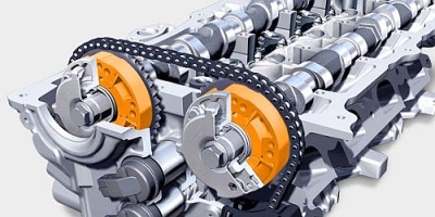
The photo above showing the 2 timing chains on that engine…
one of the high end Dodge (now RAM) pickup engines has 3 timing chains, a failure of any one of them munches a lot of components. (and yes, I’ve seen one that failed).
Actually no for example some versions of the Nissan VG V6 are of a non interference design.
Sorry hit the report button by mistake. Nothing wrong as. Far as I’m concerned
the valves are spring loaded to come back to a default position..so failure would be a closed valve which means no combustion..
Yes it’s just a coil of wire and a metal piston but to make it such that it will have a long enough MTBF to be considered for a production engine will raise the cost far beyond what the market will bear. All sorts of marvels are possible when it comes to automobiles however the real miracle is that they can make what they do affordable.
^^^ This
How long do fuel injectors last?
What sort of forces does a fuel injector face?
Hundreds of millions of cycles (mechanically and electrically) with enough spring force to close the needle valve enough to be liquid tight at 30 to 40 psi fuel rail pressure.
Forces would be far greater working a valve by at least an order of magnitude.
because solenoids in cars that get used a few times a day don’t wear out and need replaced??!! get real.
Haven’t F1 engines/power units been cam-less for quite some time now?
No: http://formula1-dictionary.net/pneumatic_valve_actuation.html
But they use compressed gas instead of springs to return the valves. Fully camless systems were/are apparently forbidden (bottom of that page).
And this is why F1 is ever less relevant to the real world. Any time an innovation is “too good” and gives too much of an advantage, they ban it. Any time incremental progress makes the cars too quick (and therefore dangerous), they add some arbitrary artificial limitation. It’s basically become a competition between the regulators coming up with newer and stupider hoops to jump through, and engineers trying to jump through those hoops most efficiently.
Absolutely right. When I was child (70ties) I think there were only general rules like engine displacement and measures of the car. Now its exactly like you describe. I barely understand why the people still like to watch it.
Even in the 70s there were lots of restrictions on what could and could not be done. F1 has always been a battle between the rule setters and the designers. And I like watching it because even with all the regulations it’s still a bloody fast car moving around a track at a ridiculous speed, driven by some very good (and some not so good, but still much better than most) drivers, backed up by a massive team of very smart engineers. And yes, “strategy” is almost as important as who can drive fastest, and yes there is a massive difference between the top 6 (Mercedes, SF, RBR) and the rest of the field, but there’s still lots of very real racing happening.
The FIAT multiAir engine ( http://goo.gl/77Pb8P ) seems like a step in the right direction. But I suspect that electric cars will have surpassed ICE cars before a true camless design wil be feasible.
Don’t you mean “driverless electric flying cars” will have surpassed ICE before…
B^)
Suprised the author missed this. The valve actuators are there on this design, albeit for only half the valves.
It shows a relatively simple design which does not require a large complex hudraulic setup.
Possibly a high pressure common rail with an accumulator to work. The pump would have to be able to keep up with the demand.
This is a bit more complex topic than that. Modern car engines are all interference design – i.e. if the valve timing is only a little bit off, the piston will crash into the valves and the engine destroys itself. There are reasons for this – mainly size and things like fuel efficiently (non-intereference engine needs to be larger and doesn’t burn the fuel as efficiently compared to interference design with a higher compression).
If an EFI controller fails, the worst thing that can happen is that the engine stalls or burns fuel less efficiently. However, if the valve actuators or their electronics fail, the result will be disastrous and very expensive (almost always an engine replacement). That is the main reason why these engines were no widely deployed – the reliability is simply not there and the purely mechanical systems are cheap and work well enough for most situations.
http://yourcarangel.com/2014/07/interference-engines-complete-list/
That list is FAR from “Complete”
What about making the valve move AWAY from the combustion chamber when opening, rather than pushing it INTO the chamber? Why does it have to be less efficient that way?
Hmm… Speaking before thinking… I suppose the combustion-pressure would be too much to hold with such a valve configuration. I knew the design of modern IC engines was pretty-well worked out.
He fumbles! …He recovers the ball!
B^)
Sealing issues and force requirements I’d suspect, pushing into the cylinder means the force of combustion pushing and sealing the valve and against it’s seats. To pull the valve in means you’d have have to hold it there against the force of combustion and to seal a moving cylinder against those pressures.
Depends when a cam sprocket jumps time and the piston contacts the valve it is pushed back against the rest of the valve train and the engine binds until something bends or breaks such as the valve,rocker arm, push rod, or the piston crown.
In a camless system the only force holding the valve would be the magnetic field of the solenoid and the inertia of the valve so piston contact may not be as damaging.
Dammit! That’s the second time I hit the fucking report button trying to scroll
My phone down. I’d quit drinking right now if I thought it would do
Any good
The idea of a camless engine has been around forever and the big issue has always been finding an actuator system that is at least as reliable as cams, and reasonably simple. The former has kept solenoids at bay, the later variable hydraulic systems. While things are looking up, it may be too late, as indeed the future is likely to belong to electrics, for passenger vehicles at least.
F1 use pneumatic valve springs as with with the normal spring loaded valves they “float” open for too long at high rpm. However they may still be cam actuated. See http://scarbsf1.com/valves.html for some details. They may be restricted from going camless by the sports technical regulations. F1 is massively regulated in terms of what they can do. Allegedly this is to reduce costs but the teams still find ways to spend massive amounts finding smaller and smaller loopholes.
What about http://www.coatesengine.com/ I’m interested to hear your thoughts about this
The valve balls are still on a camshaft.
I think the concept of spherical rotary valves would work well with rotary actuators.
It’s the valve springs that take horsepower and torque to operate, without the springs the camshaft can be rotated with your fingers
Doesn’t this neglect sealing of the valves? This now has to done with a sliding valve across an inlet, rather than two surfaces (valve and seat) simply sitting on each other to seal.
There might be other reasons why this hasn’t taken off, though.
You (could) have the cam pull the valves closed also, but the advantage of springs is they compensate for wear.
I’d love to lay my hands on 8 or 16 of the freevalve units, controlling them would be another matter but imagine the likes of a megasquirt3 or similar with a valve timing mapping table being adjusted in real time to demands, boost level, fuel injection quantities etc. I’d just make a new head from raw stock to use them to fit my existing (drag) race bike with no limitations around how many valves or their placement for maximum casting strength but still line up with the lobes of the cam.
Dyno setup might be fun mind. But bring it on. If I ever finish converting my water brake to closed loop in the meantime :)
What about the rotary?
I’m afraid that it’s not terribly efficient and wouldn’t work well as a car engine. Also, they stopped making them about a hundred years ago:
https://en.wikipedia.org/wiki/Rotary_engine
Hundreds of years you say?
https://en.wikipedia.org/wiki/Mazda_Wankel_engine
Who said anything about a Wankel engine? The word used was “rotary”.
A wankel is a rotary engine. Now if you said rotary piston engine …
http://lmgtfy.com/?q=rotary+engine
I was asking myself the same question the whole article. What about the Wankel? Mazda made some very good ones. I heard they are very smooth when accelerating.
Also, the rotary piston engine used in airplanes? They were used in WWI. Camless engines have been around for a long time.
There are rotary engines and radial engines. A rotary engine uses a fixed crankshaft and spins the entire engine around it. Mostly used in some early 1900’s airplanes but there was one low production car with horizontal rotary engine in the back. There’s only one running example and it’s been hot rodded. It was the lower priced 3 cylinder model but the current owner found a five cylinder engine to upgrade it.
Radial engines have the cylinders arranged in spokes like a rotary, but spin the crank like any other normal piston engine.
So the Wankel is an article all to itself -The materials science problems with apex seals are amazing.
One small part of what made the RX-7 what it was. Near perfect 50/50 weight distribution, sequential twin turbos…
/swoon
There are commercial camless internal combustion four-stroke engines without cams. Wankel aka Rotary.
Wankel: all the inefficiency and environmental damage of a 2 stroke with half the power and reliability!
They’re quite fun though.
What? They easily have similar power!
Wankel is not that unreliable. The problem is, that they need more maintenance and care than piston engines, because wankels inject oil into the combustion area to lubricate all the seals. Which means that you have to refill oil quite often. If you don’t do that, the engine will run without oil. Running without oil is bad for any sort of engine. Of course some douche who buys himself an RX-8 with a rotary to show off and beat it like mad without having any idea on how to take care of his car will end up with a blown engine and be crying all over the place “cause that would never happen with a non-rotary”. But you’ll never hear from the guys that know what they do. Because they’re just happy and busy driving their awesome car instead of moaning around on forums.
Yeah… thats why 15 year-old RX-7s are still highly sought after for certain motorsports.
Pretty much what I expect from you though- professing an opinion on something you know nothing about beyond repeating what you have heard from the equally clueless.
nice article
this dude has been at this since 2000 or so. http://www.evicengines.com/index.htm. there is video of some of these things running and revving on his page. well worth the read.
What about it? What about the inefficient, loud, polluting, dirty, heavy, complex and unreliable ICEs?
Ultimately the one property of ICEs that is difficult to replace is the energy density of its fuels and unless that changes, ICEs will always be a factor in vehicle prime movers.
Unreliable? I think not.
Another limiting issue is the power consumption to servo the valves at very high accelerations. Specifically, it can take more energy to flap the valves than you gain by doing so.
You need to ‘flap’ the valves whether you use a cam or a solenoid. Same energy delivered to the valve. The difference is in the efficiency of the value actuator. Electric motors can be pretty efficient, but given that we don’t we haven’t seen the commercial automotive solution, I don’t think we know how efficient that solution will be.
It’s not the same of course. Back EMF will drive up the energy requirements for a solenoid as the frequency of activation increases.
Isn’t friction analogous to back-EMF in mechanical vs. electromechanical configurations? Higher RPMs fight against the viscosity of the oil as well as any mechanical friction and of course the springs get warm from being extended and compressed repeatedly.
It may be analogous however that does not imply they are equal in magnitude
Maybe some of the back EMF can be dumped into an adjacent valve cycle to reuse the energy. If the phasing is calculated accurately and mechanically offset this could be more efficient than a cam losing energy through friction and spring force. Could lead to some interesting cylinder configurations.
Back EMF returns energy rather than consuming more energy. When electricity is connected to the solenoid, it’s converted to linear kinetic energy via magnetism. Once electricity is disconnected, the core may still be moving due to its inertial mass. As the metal keeps moving past the coil, some of that kinetic energy is converted back into electricity, like a generator. The main problem with back EMF is overloading the transistor that drives the coil. A flyback diode will protect the output transistor, but that energy can be captured and used instead, like with regenerative braking.
If we’re going to reinvent the automotive engine, why not just go full electric BEV?
One word: Range. BEVs don’t have enough. Gasoline is around 10kWh/kg. Batteries at best are 1/20 of this. See https://en.wikipedia.org/wiki/Energy_density
There is still a need for automotive ICEs, although if you go to full series hybrid then all the complications associated with variable loading and speeds can be tossed out in favour of a fixed-speed, fixed load motor-generator driving a battery pack. Tuning a motor of this type for maximum efficiency/minimum pollution is a lot easier than trying to compromise between efficiency/power/pollution across a broad range.
Awesome article! I actually went to school with Brian and was in his class where he made the engine. very cool design and way cool to see it featured on hackaday!!!
The Tucker prototypes were camless.
Just an engine that never made it into “production”. From the Wiki article -“overhead valves operated by oil pressure rather than a camshaft.”
They were based on a helicopter engine from a Hughes factory.
How about this: https://en.wikipedia.org/wiki/Sleeve_valve
What about rotary valve engines?
I have built several on single cylinder Briggs and Stratton engines. My most recent iteration runs very well putting out nearly double the stock horsepower. Check out my YouTube channel for many rotary valve videos. https://youtu.be/RjvYnzo0Qe0
I am currently working on building a full rotary valve head for a BMW M52B28 engine in a 1999 328is. As of today, 90% of the parts are complete. Check my channel out in a few months to see it running!
Awesome work! Subscribed!
This was designed in the 1980s.
https://www.youtube.com/watch?v=B0TkP18gZRE&feature=youtu.be#t=56.758662
Worked well.. massive horsepower..
Following some links around, I found ViVa piezo actuated values running an engine. Neat in that it is not “a coil of wire” as an actuator.
http://www.vikingat.com/vivapiezoactuator.html
Video here:
https://youtu.be/rb5Dap9BdpY
Now that is awesome!
Camless is a massive pain in the ass. First, they pretty much need to be a desmodromic design (powered opening and closing) for ideal control of the valve timing, opening curve, &c. Second, a solenoid/solenoid design has to constantly consume power to hold the valve open or shut. Compared to a conventional DOHC the solenoid or valve blocks make the engine even larger for the same displacement, and the DOHC is already substantially larger than the OHV engine for the same displacement. The only one I know of that is worthy of note uses a solenoid actuated complex hydraulic circuit (so now you need constant hydraulic power as well) to avoid constant electrical consumption through a clever valve arrangement that moves the valve under hydraulic pressure, which makes for a bulkier and more complex unit than solenoids or DOHC or OHV. It’s really only suited for high speed diesel engines (what trucks have) as a gas engine currently spins far too fast for it to be reasonable. At the moment low speed diesel engines are camless, using hydraulic exhaust valves and the two stroke diesel cycle.
You’re almost better off putting more research into the wankel engine to help the fuel consumption (it already does an amazing job of power output for the size) to avoid cams, timing belts or chains or gears and to simplify the engine.
That’s probably why places looking into small range extenders for electric cars or hybrid cars are looking into the wankel to a notable degree.
You hit the nail on the head. An engine spinning at 5000 rpm will fully cycle a valve 42 times per second. Typical poppet valve engines require a closed valve seat pressure of around 100 lbs. Larger, heavier valves and higher revs require much more spring pressure to overcome the inertia of the moving valve. Roller cam race motors commonly exceed 300 lbs of seat pressure when the valve is closed. That number is close to double when holding the valve open. Electrohydraulic solenoids can handle those pressures but fail to give the response needed for even at modest RPMs which is why most of the software cammed engines are low rpm diesel. I can remember International rolling out an electrohydraulic valved engine for the Pikes Peak hill climb several years ago with limited success. Electrically spun camshafts have some merit but indexing a cam with 8 valves, each with 100lbs of seat pressure, can be a tall order too. Poppet valve engines seem prohibitive to the whole concept. A non-interference design with ball type valves seems like a much better build platform and would be better suited to reap the benefits of infinitely variable valve timing aka a really wide power band. This would also eliminate some of the other rpm limitations and accuracy shortcomings inherent in the reciprocating valve system. I like the rotary piston engines for their light weight and simplicity but they have not proven themselves to be very reliable in traditional automotive applications. They are certainly RPM monsters but don’t make much usable torque until you really wind them up.
GM kicked out a press release about a “Helinoid” (hellically-wound solenoid) -controlled valve train in the late 70s or early 80s. I think Popular Science might have run it in the back pages where they pretty much just reprinted press releases back then. :-) A few minutes of googling and it seems it may have been developed at Lotus (which was somehow tied up with the General around then). http://www.eng-tips.com/viewthread.cfm?qid=128000
Anyway, I think GM may have said something like “it’s more interesting for rapidly developing camshaft profiles than it will ever be for actually making a running engine”. Then again, progress marches on. Engines really stank back then.
Are there maybe patent issues that are preventing companies from exploring this space?
Not likely. When all is said and done the potential gains are not worth the overheads that this concept creates in those cases where it’s not already being applied.
The line “From there it’s just a matter of creating a control system” makes me think of South Park:
step 1: get underpants
step 2: ???
step 3: profit!!!
There are too many people who refer to things like control systems as these, on the one hand trivial things to develop, yet on the other hand this magical glue that will solve all problems.
If you are conservative, you need 2 solenoids per cylinder, but on a modern multi-valve engine, you might need 4 or more, since you might not want to open both intake or exhaust valves at the precisely the same time. That means in the simplest case (we’ll ignore 3-cylinder engines), you probably are looking at 16 solenoids, associated wiring harnesses and electronic switching. Let’s not forget all of the gawdawful noise that switching those solenoids is going to kick up, so now you’ve got chokes and filtering, yadda yadda. You need to make the cores of the solenoids really permeable so that they can be small, but you also need to make them really hard, otherwise you will get mechanical creep in the plungers over time with your solenoids each firing thousands of times per second (and about 400 times per second just at idle), throwing things out of alignment – unless you add some sort of fluid coupling between the solenoid and the valve (more complexity). Throw in the tolerances of electromechanical components, and you either need hella precise parts or a good tuning procedure to tune out variations…
The list goes on and on. With electric cars coming down in price (they’re not there yet…), the last thing that ICE vehicles need to be is more expensive. All of the engine manufacturers already are set up for camshaft production. Does anyone really think that the internal combustion engine has so much life left in it that any manufacturers are going to make any of their investment back before production ends?
Finally, WRT to legislation: what would the motivation be? switching from carburetors to EFI dramatically reduced hydrocarbon emissions and, with them, smog. What public good would we realize with camless engines? Most car engines spend most of their lives operating in a very predictable, narrow band of operating conditions, so optimizing camshaft profiles for that scenario is not a big deal. I don’t see any major efficiencies to be gained from camless engines. Generators similar diesel-electric systems run at even more controlled speeds/loads, the whole point being to maximize efficiency, so the benefits of going camless for them would be even less.
Is it an interesting topic? Of course. Is it a solution looking for a problem? I think so.
“with your solenoids each firing thousands of times per second (and about 400 times per second just at idle)”
RPM = Revolutions Per Minute.
The advantage of a camless engine would be true variable valve timing – the gains would be similar to modern VVT systems but more dramatic. Also misc benefits like easier starting and cylinder deactivation.
I’m curious how you got 400 times per second – it doesn’t line up with my math. Assuming a 1500 RPM idle speed, that’s 25 Rotations per second. On a four stroke engine, that would be 12.5 valve actuations per second for a single valve.
“No automotive manufacturer has been able to eliminate the engine’s camshaft in a piston powered-production vehicle.”
Not necessarily true, I own a Sears Allstate Puch and the cylinders are ported so no cam and that was a production vehicle in the 60s.
http://home.sprynet.com/~inniss/searsmtr.jpg
The camshaft is still there; its functionality has just been integrated into the crankshaft.
You could never truly be rid of a camshaft by your definition.
I knew when I wrote that sentence someone would show up with a weird and wonderful vehicle I’d never seen before. You sir, win the prize! At it’s core though, the puch is a 2 stroke engine. I’m really trying to cover 4 strokes here.
He probably can’t hear you if its as loud as the dkw split single racing motorcycles that the design was also used on. Ancedotal statements from the time mention being able to hear them racing on the Isle of Man TT circuit from the british mainland, 16km at the nearest point :-)
https://en.wikipedia.org/wiki/Split-single
Not all that loud, Harleys are louder than the puch but at the same time I never heard myself at 55mph from a distance which is like having a wood sander between your legs at that speed :D
weird and wonderful? can’t get much better than this, yes i know its diesel and its 2 stroke,but when i feel like looking at amazing but ultimately outdated engineering marvels this is probably the best example. apart from nuclear fusion as a power source of course……
may help if i included the link.
https://en.wikipedia.org/wiki/Napier_Nomad
Most two-stroke engines have no cams. They also haven’t been used in cars (except VERY rare exceptions) since the 1950s, and were very rare even then. This article covers four-stroke engines.
The east german “Trabant” car had a two stroke engine. Built until 1991.
the engine development division of rover called powertrain technologies had a camless engine in the prototype stages, I rmember reading lots about it years ago, a quick google now reveals lots of 404’s/
technology lisenced from a company called camcon IIRC
Gas turbine anyone?
Finally I can toss that old degree wheel.
Think outside the box here. Why don’t they use slide valves like these:http://www.google.com/patents/US5694890
You can use smaller actuators becouse you don’t have to fight the dropping pressure on the inrake stroke, and you can afford a little software sensor glitch without destroying the valves and pistons.
Slides, rotary valves, everything is on the table. My goal with this piece is to get people thinking – and building.
Camless valve actuation and variable valve timing schemes have been batted about just about forever. I can recall discussions among gearheads in the early Sixties, and I strongly doubt there is a single engineer working in the ICE field that hadn’t given it some thought at some point. The fact is that this is an area where the returns diminish very quickly and thus economically there are only a very few applications where they will ever be practical and those are being exploited. Automotive engines are just not one of them.
The problem boils down to carbon and distortion ruining the mechanism.
Sleeve and rotary valving has been tried quite a lot through history, and always the same result of poor sealing after a period of running, or seizure. The coates engine is showing promise currently though.
http://www.douglas-self.com/MUSEUM/POWER/unusualICeng/RotaryValveIC/RotaryValveIC.htm
I was in a club at my local community college back in 87. We were talking about trying this kind of thing and even drew up a few plans, but as all things go life got in our way and it never happened.
May be worth checking out Nissans VVEL implementation of the intake cams.
Carburetor -> EFI … BIOS -> UEFI … Everything was better in the old days…
No. What should have been better with the old carburetor? And think of the ancient light bulb,, it’s good that they are phased out – I prefer LEDs, they produce less waste heat and I have a choice of the color temperature.
I have been designing and building aftermarket ECU’s for high performance engines for years, including direct-injection setups. I –LOVE– EFI, and I love cars, and I certainly agree there is tons of room for vast improvements in engine controls and combustion efficiency. however i have a HUGE problem with the authors comment:
” What’s missing are the regulations to force the issue.”
More government regulation does not fuel the engine of capitalism. If the electronic valve technology can be used to provide vast improvements in engine efficiency and power, then the free market will demand it – and the small engineering startups will be heavily financially motivated to supply it. Government side regulations are not the reason why EFI “took off” – it is because the damn cars simply run much better – and it is actually cheaper to produce and EFI system than an impossible-to-build mechanical carburetor that would give you all of the same benefits as EFI.
It drives me nuts when educated people believe that restrictions – not rewards – entice people to strive for better.
Hi Louloulou! I definitely don’t want to see everything about cars regulated to death. However, the move from carbs to EFI definitely happened in response to emissions issues. see Wiki: https://en.wikipedia.org/wiki/Fuel_injection#Electronic_injection for one source. We also do need SOME regulations on factory engine performance. The recent VW case is proof that manufacturers will attempt to find any way to get an edge- legal or not: http://hackaday.com/2015/09/23/ethics-in-engineering-volkswagens-diesel-fiasco/ There have to be some sort of “teeth” to ensure we’re not trashing our air quality with every car that rolls off the line. China is working to fix this sort of problem: http://ourworld.unu.edu/en/china-to-scrap-millions-of-cars-to-ease-pollution
You are already seeing the effects of over-regulation. Take the CAFE standards for example. Some idiot panel of GS-14 government bureaucrats, and their associated special interest and high $ contractors, whom have never built anything in their life, and whom never took a physics class, “determines” that the fleet average mileage must be 35 MPG by, say, year 2020. (All of this studied at HUGE taxpayer expense) Well, its simple physics folks. Heavy thing hits light thing, light thing goes flying in a different direction very fast with hurt people on the inside. To meet thees standards the mass of the vehicle must be reduced as much as possible. Yes, there are better materials and “crumple zones” – but in the end the cars end up lighter. That’s all well and good — if only you could reduce the mass of the 18 wheel trucks, guard rails, and trees that cars tend to run into. So, as a direct result of government regulation you now have more highway deaths, all for some marginal MPG improvements see:
http://www.americanthinker.com/articles/2010/04/death_by_cafe_standards.html
http://www.nationalcenter.org/NPA546CAFEStandards.html
The VW “cheating” is also an example of the cause and effect of over-regulation. What VW did was wrong, but lest at least explore why they were motivated to cheat.
The standards are so ridiculous that they can’t be met AND still produce a car that most would be willing to buy for a reasonable price. This is because the regulations have become political, and are not based on sound science. Look at diesel engines for example. The eco-people and the fed’s love to pick on them because they emit black soot. Its SOOT folks! –I.E. small carbon-chunks, the stuff we are all made out of!! Its not CO, its not (much) NOx, but because you can see it as black smoke, the uneducated think that is bad stuff that is killing baby sea-lions. So, now, by federal mandate, we need to add a particle filter system to the engine. The problem is that the particle filter clogs up every few miles, so to un-clog it we then program the engine to pump super hot lean-burn exhaust into that exhaust filter to “burn” the soot. Then this has the unintended consequence of making a LOT more NOx emissions (from the soot filter, not from the useful engine combustion) So then we have to add an SCR (urea) injection system to get rid of the NOx and turn it into N2 + H20. – Except we are not taking in to account the fact that this chemistry is not perfect either, and we now exhaust isocyanic acids and a host of other crap in to the air – these gasses have yet to be regulated, and have yet to have their long term health effects evaluated, but don’t you worry, someday that is going to further complicate and regulate the issue.. See ? It only gets worse – not better..
So, in the end, VW decided to beat the feds at their own game, when the test parameters we detected the engine ran in a limp-noodle mode, (one you would never buy as a consumer) but passed the tests. They also saved $2,000 dollars of tanks, pumps and filters and made the car easier to service. Yes its wrong, but do you see how over-regulation may have lead to some bad choices being made here?
I am not saying we don’t need a set of standards, but we do need to heavily scrutinize the addition of any set of regulations before the laws of unintended consequences produce a much more hazardous condition than the one we are trying to fix. In general education beats regulation. If your car was known to be a pollution making death machine, no one would buy it. You would not need federal regulations.
Its just like the mandate to do away with conventional lightbulbs.
Sure- ccfl and led bulbs use less energy when it gets to the end consumer, but what isn’t factored in is the added energy and resources to produce these bulbs. Conventional light bulbs are relatively simple devices- a bit of glass formed in one simple step, a bit of filament and a conductive metal cap… CCFLS? More glass, a more complicated process to shape and form, more hazardous chemicals, ballast electronics, etc. LEDs? Not even getting into THAT…
Then you add in off-shore manufacture because that’s cheaper despite a dirtier process, reduced manufacturer quality from beancounters subbing out components to save a nickel over 10,000 units and get reduced lifespan for the trade.
In the end you end up with something far more polluting and far more hazardous… I wish cheap chinese ccfls and leds would start exploding in sockets and burning down houses so maybe the issue would get attention like all the exploding batteries get.
Actually no regulation comes without the approval of (at least some of) the industry players. Those that developed the EFIs pushed for some regulation to ban older models and make the customers go to them and make everyone else play catch-up.
The VW scandal came not because they can’t fulfill the regulation, but because they saw too late that the technology they used was limited and was too late to change the HW (the same root cause as SW that gets released “too early”).
After working for BMW and MINI, I can attest that solo if those vehicles are shipped to the docks, where they are tested, with a special “shipping” flash on the ECU. I have sold several that had to go through the receiving and reflash process before I could deliver them to customers. This made zero sense to me, until the news about VW made headlines…
I would point out the transmission in my neon is all electronically timed and controlled through a solenoid pack controlled via a separate tcu(transmission control unit). I have never ever seen a solenoid in one fail. Not to say its never happened lol. Rather its usually the springs lose their compression and cause a chatter in the valves they control. Wouldn’t be much of a stretch to adapt that kind of technology to this issue.
Mind you the 41te transmission first came out in the late 80’s
Shift solenoids don’t need to work anywhere near the duty cycle valve solenoids would. Just consider the frequencies involved and it is clear this is a whole other domain.
And I would point out the following things about transmission vs engine:
1. active for longer periods (100ms range) vs. 30ms for 1000rpm engine
2. number of activations is in the range maybe 1/s (worst case city very aggressive driving) vs 16/s engine idle
3. work with much lower and slower pressures (in an engine, you will have 9-10bars at end of compression, before detonating the fuel)
4. transmission solenoid failure will result in disconnection, whereas engine failiure can lead to sudden stall, which the transmission has to disconnect, otherwise wheels will lock-up. Engine damage is implied.
From 1. and 3., there are 2 electrical conclusions: they need a lot (10x-100x) of electrical power to do the job. Which leads to thicker wires, massive transistors (with massive heatsinks) and massive EMI. In short…..way too expensive.
The concept is nice, but you should already know that things don’t scale in linear fashion and sometimes researching another domain is less expensive than developing this (looking at you, electric cars!). Why use tons of electricity for valves when you can sent it to the wheels?
It’s a big stretch from a transmission ECU / spool valve controller.. The engine valves are quite massive in comparison to the spool valves in a cars transmission, and must move much, much faster many more times. (3600 RPM’s = 30 valve cycles per second) Your transmission averages a few cycles per minute.. In addition forces are much, much larger than in a fluid control valve. There is a reason why engine valve springs are so massive – you need a lot of pressure to hold them closed. Cylinder pressure in a heavily loaded engine can exceed 1000 PSI. If your valves are not held tightly closed the escaping gasses act like a blow-torch and cut groves in to the valves, “burning” them. In addition, if you really want to make the engine run to its full potential, you need to vary the valve lift profile, you cant just “bang-bang” open-close the valves. That wont work. That’s why you see VVT-LI engines, variable valve timing and lift height control. The idea is that you are trying to maximize the velocity of the airflow in the intake manifold suck that you get a “hammer head” effect that squeezes more air into the cylinder – and just before the “squeeze” air starts to reverse direction across the valve, you want to close it shut. What complicates this is that the piston’s velocity is constantly changing, (in a sinusoidal manner) so you need to change the valve profile in a manner that is non-linear if you want to achieve laminar airflow at high velocity.
To do this right, you need positive position feedback control on the valves. Yes, voice coils could be used, but you are not going to be able to use neodymium magnets – they permanently loose their magnetism at temperatures over 230C – so you are now left with flew low cost magnet options.
I am not saying it’s impossible – I am just saying that the very talented engineers at all of the auto makers have put lots of time in this idea, and have not yet come up with an economically viable solution — yet.
“No automotive manufacturer has been able to eliminate the engine’s camshaft in a piston powered-production vehicle.”
Quite a few have made two stroke engined cars, and they have no camshafts. But they had very bad emissions too. I think you forgot the ‘four stroke’ in your title.
But apart from non-constructive criticism from me I have too wondered why we still got cams. With fully controlled valve system that was independent of crank position it would allow the removal of the butterfly valve in the inlet track using the valves them self’s to restrict air intake as well as altering compression ratios. Both these have been done with mechanical systems but seems would be far simpler with software and some valves. My only question is that could such as system run at 8000rpm or above without self destructing? My motorcycle real line is 15500rpm! Could it do that?
Most diesels have camshafts but (most – some odd old Mercedes engines (240D) did control airflow primarily and fuel flow indirectly) don’t have any restriction in the air intake tract. Speed and power are regulated entirely by the amount of fuel injected. In principle, that could probably be done with a direct-injected gasoline engine too, but it would be very rough and probably wouldn’t work well at high engine speeds (very high speed diesel reaches maybe 4-4.5K RPM). The butterfly allows finer adjustment of air-fuel ratio, which is important for gasoline engines (especially, these days, for emission reasons) but less so for diesels which always run with excess air. Again, camshafts would still be needed to operate the valves absent some demon tweak like F1 engines have used.
All bmw valvetronic engines regulate airflow via valve lift, in normal operation the throttle body is full open at all times, only when a problem is detected in the valvetronic actuator/sensors then the car reverts to using the throttle.
“No automotive manufacturer has been able to eliminate the engine’s camshaft in a piston powered-production vehicle.”
Fiat have come extremely close with their Multiair systems. The camshaft does not directly control the inlet valves. There are several videos explaining it.
I was hoping this would be more about using non-standard valves as well but it seems everyone’s concentrating on the typical approach. I seem to remember some designs from almost 30 years ago that used butterfly valves(I think it was the Yamaha V-Twin design, IIRC), and I’ve often thought of a sliding/rotating port approach. Of course then you could delve into the Wankel rotary engine territory if you start along that path.
I believe the fiat 500 has a calms intake valve
Multiair was never fully camless
Formula 1 cars use pneumatic actuators on the valves, providing up to 20,000 rpm, but usually limited to around 12,000 for fuel efficiency reasons.
synchronicity: the simultaneous occurrence of events that appear significantly related but have no discernible causal connection: such synchronicity is quite staggering.
See also: the wrong word to use when describing the operation of an engine, particularly one with camshafts and timing belts/chains.
Why not just replace the camshaft with really teeny weeny two stroke engines driving the valves? (Hey, I’m pitching. :) )
Because then you need teeny-weenier cams for those engines!
Its a 2 smoke, no cams
Teeny-weenier reed valves then.
So… um… wtf happened to [read more]? Just put the whole article right in the summary page now?
Multiple times in the last couple weeks this has happened. Typos, grammar errors and now walls of text? HaD really doesn’t care about at least having the appearance of a good staff of writers, does it?
There are those liquid piston engines….basically simialr to Wankel but without apex seals. Running a hybrid Otto/diesel cycle iirc…. Would love to see a working engine….
wtf HaD? Just doing away with [continue reading] and putting the whole wall of text out front? As if the poor spelling and grammatical errors arent bad enough…
Maybe someone needs to be put in charge of reviewing submitted articles and docking pay based on errors? Something that hurts… $5 for each spelling error, $5 for each grammar error… $10 for messing up page formatting (walls of text that aren’t broken with [continue reading]…
I know HaD writers are essentially volunteers with a low rate of compensation, but compensation should be based on quality- if you lack in quality then you should lack in being compensated.
Just like in school- you don’t get an ‘A’ for handing ANYTHING in. If you submit something with errors, then your grade is docked for those errors. If you want an A next time then maybe you should proof-read your work before handing it in.
Carburetors lasted into the early 90’s. By 1992 in the USA there were very few cars sold with carbs. What finally did them in was California’s CARB agency. They developed an evaporative emissions test designed to fail any vehicle with a carb.
It was called the SHED test. Sealed Housing Evaporative Determination. The test placed the vehicle in a sealed ‘shed’ then lowered the air pressure a bit below ambient. Then the amount of VOCs from the fuel inside the shed were measured. Pass a law setting the allowed evaporation to less than that and all vehicles with a carb fail the test.
Electronic controled valves would see an improvement in engine performance and drivability as the article suggests but rather then focusing on the reasons why it can’t work. Let’s be a bit more creative and work out a better solution.
Moving from a mechanical valve train to an electronic one may also directly give a power increase just from removing the energy required to push against the springs. There would be more load imposed on the electrical system but maybe that won’t be as much – with a better valve design at least.
http://www.gizmag.com/duke-engines-axial/33631/
Sounds pretty cool, swashplate instead of crankshaft, running 14:1 compression on 91. I have also seen a camless opposing piston engine somewhere that had quite exciting claims but cant find the link.
Simply a GM air conditioning compressor that they added spark plus to.
Gemini aircraft diesel engine?
http://www.geminidiesel.aero/why-diesel/gemini-diesel-solution
http://www.freevalve.com/
Is the right question being asked here? How about dispensing with valves altogether?!
Here is an awesome rotary ‘piston’ engine (DynaKinetic):
https://www.youtube.com/watch?v=5m1meR3dueo&feature=youtu.be
http://newenergyandfuel.com/http:/newenergyandfuel/com/2014/06/25/how-the-gotek-energy-engine-works/
http://gotekenergy.com/
And here is a Junkers-Jumo type engine:
https://youtu.be/_QTfvIfsjJw
http://achatespower.com/
Both are essentially advanced, two-stroke direct injection engines with greater efficiency than anything currently in production. The first one is an extremely efficient (reportedly 53%) low reciprocating mass rotary (71% less total mass than a standard ICE piston engine) while the second is a Junkers-Jumo style engine that, while not directly providing efficiency numbers, infers a mid-high 40’s% efficiency with a slight size/weight/cost reduction (compared to a diesel) of around 10% from what I could tell.
While I would happily replace any engine on my farm with either of these, the Gotek Dynakinetic engine looks to me to be an amazing piece of engineering!! Who wouldn’t want a nearly vibration free (http://gotekenergy.com/?page_id=44) 1.5-liter four-cylinder engine that is 6 inches wide and 12 inches in diameter (with the likelihood of producing >300HP at <5,000RPM)?
doesn’t it still suffer from the same problem as the wankle engine? ie. the seals.
No, the only similarity between it and a wankel are that it is a rotary engine. The Gotek Dynakinetic engine has rotating end caps which create the ‘cylinder’ walls, greatly reducing seal wear. A Wankel rotor side seal swept the entire sidewall but here the flap side seals need only sweep the distance of travel, which is quite small at the hinged end and even slightly less than a standard piston engine at the other end.
Also the seal between flaps is a simple sweep in a true circle – and since the engine is also naturally well balanced, this seal should fare as well or better than a standard ICE since it will see no axial inertial moment (eventually resulting in piston side slop). The only reciprocating parts are the flaps and connecting rods that are counterbalanced opposite to one another. With all four “strokes” completed in one revolution the engine should be very smooth indeed.
Another advantage over the wankel is that the wankel suffered from the same portion of the combustion chamber always being in combustion. It is quite challenging to seal a rotor that sees vastly different temperatures. In the wankel, intake and combustion occur simultaneously, but in different parts of the housing. when the top of the housing was relatively cool, the bottom of the housing was much hotter. From a sealing standpoint, this is problematic, as you are trying to create a seal with metals that are operating at significantly different temperatures – in the Gotek Dynakinetic engine, the cylinder ‘walls’ cycle through all phases of the combustion cycle. While it is true that the same part of the ‘head’ sees combustion in this engine, it’s increased efficiency (less heat loss/transfer), the fact that the rest of the engine rotates (distributing heat/cooling effects), the use of advanced materials (composites), and the strategic placement of coolant jackets to help even out the heat load, this problem is significantly reduced.
FYI – I have no affiliation w/Gotek whatsoever. I am just a systems engineer and former motorhead that stumbled upon their website and became enamored with their current prototype engine…I hope it becomes a reality, it would make an awesome Hybrid – on the ground or in the air!