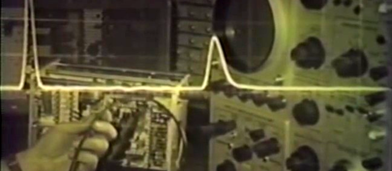
This great old video (embedded below the break) from Tektronix in the mid-60s covers a topic that seems to confuse folks more than it should — transmission lines. We found it on Paul Carbone’s blog, a great site for aficionados of old analog scopes in its own right.
As with many of these older videos, the pacing is a bit slow by today’s standards, but the quality of the material eventually presented more than makes it worth the effort to reign in your ADHD. For a preview, you can skip to the end where they do a review of all the material.
They start off 5:31 with a pulse travelling down a wire pair, and take a very real-world approach to figuring out the characteristic impedance of the line: if the pulse was created by a battery of 9V, how much current is flowing? If the DC resistance of the wire is zero then there should be an infinite current by Ohm’s law, and that’s clearly not happening. This motivates the standard analysis where you break the wire down into distributed inductance and capacitance.
Of course they do the experiment where you inject a pulse into a long loop of coaxial cable and play around with the termination at the other end of the line. They also measure the velocity factor of the line. Our only gripe is that they don’t tap the line in different places to demonstrate standing waves. The good news is that we’ve got YouTube (and [w3aew]) for that.
If you’ve got 23 minutes to spare, and are curious about transmission lines or just enjoy the soothing voice of a trained radio announcer reading out values of various termination resistors, this old gem is just the ticket. Enjoy!


The narrator kinda sounds like Morgan Freeman.
I was going to say Kurtwood Smith… http://www.imdb.com/name/nm0001748/
No, no, it’s Ze Frank!
https://www.youtube.com/watch?v=UR_byRbXxvs
Another classic video on transmission lines:
https://www.youtube.com/watch?v=DovunOxlY1k
Another good one
Good one, but be wary he got the electrical waves wrong. It’s actually the opposite – shorted line produces inverted reflections, and open line regular reflections.
Things were different back in those days, back then the arrow on a diode pointed the direction the “electricity” flowed. B^)
It’s nice to see a visual demonstration about proper line termination. It gives me a better idea of what goes on with terminators for the CANhi and CANlow lines of a vehicle’s CAN bus, or any CAN styled data bus that I have encountered.
Although, it makes me wonder how some manufacturers get away with using the same CAN terminator on a machine with a short CAN harness as a machine with a long CAN harness. Noise compensation in the controllers, maybe?
The characteristic impedance of the transmission line is the same regardless of how long it is.
Prof Greg Durgin have a YouTube channel with a full course about transmission lines (TDT and THT videos):
https://www.youtube.com/user/profdurgin/videos
Great video, although they only very briefly go over the concept of the “pulse”, and some of the physics behind it. The way that E&M is usually taught, this might be a point of confusion for many people: if there is no closed circuit, there is no current, and thus no electron movement.
Yeah, right. Your DC logic is useless here.
The circuit “closes” through the capacitance between the lines, if you want to say something intuitive. Electrons are pushed into one wire and equally repelled out of the other by the capacitive coupling.
For me transmission line theory was the way of finally understanding how RF antennas actually work (of course in a simplified way, but still).