I’ve been testing out the Raspberry Pi 3, and one thing I have found is that the WiFi antenna that was added in this new model is not especially good: the Pi has trouble connecting to my WiFi network in places that other devices have no issues. That’s not surprising, because the antenna on the Pi 3 is tiny: mounted right next to the display connector, it is just a few millimeters wide. [Ward] at DorkbotPDX agrees, so he decided to look into adding a better antenna by adding an external connector.
He tried two approaches: replacing the antenna with a tail connector, and adding a U.FL connector to the unused solder pads on the board. Both require some delicate soldering work, so they aren’t approached lightly. Replacing the antenna with an external connector produced a significant increase in signal output, which should equate with more range for the WiFi connection.
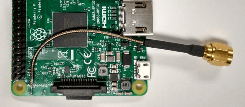
It is also interesting to note that the Pi 3 has solder pads on the board to add an external antenna connector, but that they are not used. Plus, one of the solder pads is covered by solder mask. Using these is the second approach that [Ward] used, soldering on a U.FL connector and connecting that to a small rubber duckie antenna. Again, this proved more efficient, increasing the power output of the antenna significantly.
NOTE: This hack definitely falls into “Don’t try this at home” territory. Messing with antennas voids the warranty and FCC certification for the Pi, and can cause all sorts of signal-related unpleasantness if you aren’t careful.


I’m now looking at my Pi3. Apparently, adding the second ground pad would trigger DRC or something. However, it seems that you need to desolder a 0402 resistor/cap and then solder it slightly differently for u.FL pad to get enabled. Not for most of us, though I could do it if I really really needed.
BTW, does the radio support monitor mode? Somebody please do “iw list | grep -A8 modes” and post it here.
If you have a pi3, why do you need our output?
Supported interface modes:
* IBSS
* managed
* AP
* P2P-client
* P2P-GO
* P2P-device
Band 1:
Capabilities: 0x1020
—
software interface modes (can always be added):
valid interface combinations:
* #{ IBSS, managed, AP } <= 2, #{ P2P-client, P2P-GO } <= 1, #{ P2P-device } <= 1,
total <= 3, #channels <= 2
Device supports scan flush.
Lack of resources =) I’ve got 2 Pis running at my workdesk right now, they’re doing important tasks and can’t be turned off, and they currently use all the cards with working images, as well as occupy all the HDMI inputs I have. I’m also short on keyboards&mice. Thanks for the answer!
IBSS
managed
AP
P2P-Client
P2P-GO
P2P-device
Looks like it doesn’t support monitor mode yet.
What on earth… now the basic concept of “hacking”, with no safety risk what so ever, falls into “don’t try this at home”? Oh teh noes, my warranty? Is this april fool’s day?
I just like my disclaimers ;) Obviously I wouldn’t have written it up if I didn’t feel that it would be of interest or generally useful.
I suppose if you bridge the wrong traces or overheat a component, you could kill the device or certain capabilities of it. It’s a fair warning.
Oh, and the FCC could kick down your door, though that is an exceedingly remote possibility. :P
Its a low cost board, I would argue that the simple learning experience of trying it and failing is more than worth the $35 but you would have to be quite retarded to screw it up. These boiler-plate disclaimers do nothing to improve the community and when improperly used the artificially discourage people from experimenting and learning.
“I would argue that the simple learning experience of trying it and failing is more than worth the $35” — It’s all fine and dandy if you’re swimming in cash, but don’t assume everyone else is, too. Also, it’s not $35 everywhere, like e.g. here in Finland it’s closer to $45 + shipping if ordered from an out-of-country location, and $66 if ordered from a Finnish store.
^^ This. I used to be making the bucks, I mean, at least for my needs. Right now I’m stuck at a 30k job living in NYC. I’m barely making enough for rent and food.
FC what? :) Land of the free, huh?
I agree, this should read ‘you should try this at home’, its a bit disappointing to see. Perhaps Richard should get some time with the soldering iron.
Yes, but he didn’t say you couldn’t try it at a friend’s house. Or at the park. Or dangling from a cliff. Or while sky-diving. Or scuba diving. In fact, when you think about it, he was actually quite restrained with his disclaimer.
The safety of the Pi is at risk if the person attempting to do the modifications is incompetent at working with boards and components at the scale of size. Unlikely that this mode would affect the FCC certification I haven’t read the applicable FCC regulations to know if this would be in violation of those. Those two things are something most who are subject to FCC regulation doing this mod would think about. No doubt those who say they don’t care about the regulations would be the first to call the FCC if another’s carelessness louse’s up their WiFi use.
Hackers don’t follow laws. They get the job done with the materials on hand.
The emitted power is within FCC limits.
It makes me wonder, why they designed a place to solder a proper connector, but didn’t connect it and added a solder mask over it in the first place? They should just put a space for that connector and connect it to Wi-Fi module or if FCC has problems with that, add two pads that can be bridged with solder or solder and piece of wire to enable usage of proper antenna connector. And FCC can go and fork themselves in their collective bass…
Maybe they thought it would work, but testing said otherwise. They could go back and change the board, but that would be another iteration. Compliance with the radio rules might men more testing after the board change, takes time and money. Maybe they anticipated problems, so the potential is built in, but one “can’t” be used. Maybe they decided it was simpler or cheaper to have just the built in antenna, considering many don’t have solder skills, especially at microwave frequencies.
It’s never been uncommon to lay out boards which can have various options or different size components, so one board will fit. I suppose it might be les common today with the whole thing being redone for each product run since the main components may not be available, but in the past you didn’t want things held up because you were waiting for capacitors with the right spacing.
Michael
I would guess that a non-populated connector is for FCC/CE/etc compliance testing and/or development. Compliance testing requires conducted power measurements and the samples are prepared in one of the two ways shown here (unless it has a real RF connectors, but I’m thinking anything with a chip antenna will not). You can probably rotate that resistor to connect the u.fl to the antenna as well, hook the thing up to your VNA and do a little antenna matching.
Both of those are distinct possibilities. It makes an excellent point for connecting in a coax probe for antenna tuning and for conducted measurements. It’s possible that the convenient fit with a u.FL connector is just coincidental. I didn’t bother looking at the built-in antenna’s tuning with my VNA, but I assume the designers have done their job there. There is a shunt 1.5 or 1.8pF cap near the antenna feedpoint, so they’ve done some tuning for sure. The second zero-ohm stuff is almost certainly there in case an L-network was needed.
Sorry that’s representative an attitude that could wreck a good thing. For profit companies looking to serve the larger general population, working withe the FCC to create a license free radio service is why the DIY community has access to affordable RF modifiable RF equipment. That equipment wouldn’t be available at current prices, Cost would me much higher if the market consisted of the DIY segment of society. S For me it looks to a bit arrogant or ignorant to bash the FCC on this, where they could have denied type acceptance saying the design is easily modifiable from the product that would be granted type acceptance. S it is the Pi 3 I think the old timey term for attitude and arrogance so often displayed here at HAD is don’t look a gift horse in the mouth.
Pardon my ignorance here, but does anyone know if installing the U.FL connector precludes the use of the built in antenna?
Seems like it does. From my observations, you have to move a 0402 size component to switch from antenna to u.FL.
Worse, an 0201, half the size of an 0402. Teeny tiny.
That’s probably just a zero-ohm jumper to connect the internal antenna.
With it removed the connector should be okay.
I’ve done a similar operation on an Ouya game console where I removed an internal jumper and it set the stage so to speak for the connector installation.
The connector install wasn’t all that bad and the performance increase from using an external antenna was notable.
Too bad the Ouya was doomed to failure, but that is a tale for another time…
Thank you! I thought as much, but I’d rather be sure than guess.
Yes, it does. RF stuff doesn’t really like being paralleled; by putting a connector on the transmission line with the onboard antenna in place you’re essentially putting two 50 ohm* loads in parallel and presenting a 25 ohm load to the radio. Not only will each only get a portion of the power, the transmitter will see an impedance it’s not designed for. But give it a shot, that’s what hacking’s all about. Physics and engineering aside, the goal is to improve performance, and if the performance is improved then you win.
*The antenna is likely a bit off from 50 ohms, even after tuning. They all are.
This^
I see similar mistakes made with RC transmitters where people think just soldering on random wires will make it work better, but one has to be taught antenna theory to put it into practice so makeshifts abound.
I would disconnect that internal antenna and just go with the external connection as external antennas are always always better than internal antennas. -Always, no shit.
I was going to add that prepping the coax cable for soldering can be really easy: The trick is to trim it, tin the braid part and then let it cool down completely so that the cable insulation isn’t stressed by constant heat and movement.
Thanks. My reason for asking was primarily to see if I could use both in a PiGrrl-style environment, leaving the internal for basic wifi and the external for more advanced usage as needed.
Hey Ward, here’s a suggestion: Get rid of that gif with the cat on your main page. JFC….
Absolutely do not get rid of that cat. In fact you need to turn up the volume even further.
Absolutely get rid of cats. In fact, you need to abandon your “Everyone on the internet loves cats, derp” stigma.
I hear if you give it some catnip it chills out some. Either that or starts a 20-minute Grateful Dead riff. Roll the dice.
This comment made me laugh. Good to know Ward is a Dead Head
Also take a look at Kris’s work here:
https://hackaday.io/project/10091-raspberry-pi-3-external-antenna
He’s used a more hacker-friendly approach to adding the U.FL that doesn’t involve manipulating the 0201 resistor.
Well, he did manupulate it – he removed it and shorted the traces with a solder blob =)
Yah, I totally manipulated my board’s zero-ohm resistors. When I flicked them away they went POOF, never to be seen again. =)
what kind of solder paste did you use?