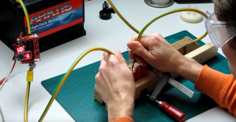
Soldering might look like a tempting and cheap alternative when building or repairing a battery pack, but the heat of the iron could damage the cell, and the resulting connection won’t be as good as a weld. Fortunately, though, a decent spot welder isn’t that tough to build, as [KaeptnBalu] shows us with his Arduino-controlled battery spot welder.
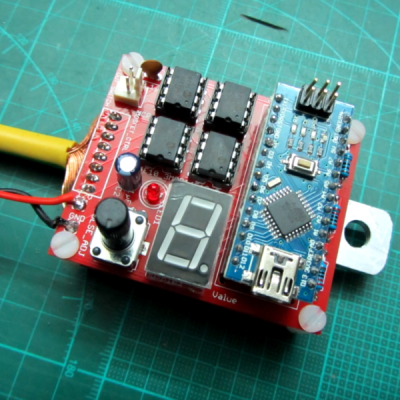 When it comes to delivering the high currents necessary for spot welding, the Arduino Nano is not necessarily the first thing that comes to mind. But the need for a precisely controlled welding pulse makes the microcontroller a natural for this build, as long as the current handling is outsourced. In [KaeptnBalu]’s build, he lets an array of beefy MOSFETs on a separate PCB handle the welding current. The high-current wiring is particularly interesting – heavy gauge stranded wire is split in half, formed into a U, tinned, and each leg gets soldered to the MOSFET board. Welding tips are simply solid copper wire, and the whole thing is powered by a car battery, or maybe two if the job needs extra amps. The video below shows the high-quality welds the rig can produce.
Spot welders are a favorite on Hackaday, and we’ve seen both simple and complicated builds. This build hits the sweet spot of complexity and functionality, and having one on hand would open up a lot of battery-hacking possibilities.
Thanks [Chris Muncy] for the tip.


This is awesome, I could even power it from one of my 3s 10AH 30C lipos!
Lipos normally have a protection circuit to block high current draws for safety.
30C 10Ah LIPos would need a 300A protection. They likely are unprotected cells, but even if they have it this current is likely not exceeded when spotwelding at ~12.6V.
Hobby lipos (think RC flying) generally don’t have any protection on them.
Protection is handled by the speed controller and even the really cheap controllers generally have some configuration options as to what voltage level they will cut out at.
The ones designed for multi-rotors do not.
I meant “safety” more so than “every”, which I never said. I’ve personally seen an old Lead Acid car battery explode when a spark occidentally detonated the exhaust gasses under a short-circuit load. And shrapnel flew away with enough force to kill. Since for “safety” there is normally a circuit to prevent overload in lipos either in the battery or in the load circuit, it is there for a reason.
On one side you see a nice crimp-ring connection. If I have the suitable tool I would make both sides like this. Also a car battery is very heavy and not necessary for puls-currents. A small battery or PSU and one if this 0,5F to 1F caps the car audio freaks use to buffer the battery voltage in the rear of the car would be a lighter and perhaps cheaper solution. Of course the price depends on the availability of surplus stuff :-)
I myself thought already about such a project. Do you control the current in any way or only the timing? I want to use capacitors, about 20 or 40 10mF in parallel and also control the charge voltage if necessary.
Reason for the massive parallel caps: I got them cheap a long time ago.
I dunno if the caps car audio freaks use can provide the high current pulses, I think they’re a bit slower to release all the current. Good enough for big bass rumbles (since a bass waveform is by definition a long, slow-changing wave), but perhaps not for welding. Of course, I could be wrong. There are high-current caps out there but probably a bit more expensive than car audio ones. Unless you know someone who’s dismantling a nuclear reactor or something.
They are supposed to have lower impedance than the car battery itself to improve the sound. At least this is what marketing says :-) Probably the quality on the market is variable. But even some tiny flash caps discharge in 1ms and deliver kW of peak power. 200A @ 12V are just 60mOhm, this is not low for a 1F cap.
Away from all theory I have already found several reports about using this caps successfully in just this application – battery spot welding. Recommendation was to use >=0,25F.
So you do not need the additional power of radioactivity for this :-)
He probably “borrowed” the already crimped earthing wire from another device. Which could make some people quite angry because of the color coding…
Kudos to the author – this is useful. However, it has a great deal of danger potential for your typical mimic who will build this without understanding the dangers associated with the large lead acid battery. Good job on the author’s part as I’m sure he understands the dangers but this isn’t the type of project that you would want to keep indoors without several added safety features… Car batteries are no joke.
A capacitive discharge spot welder is much more compact and safer by far. Dozens of the capacitive discharge welder projects have been published on the ‘net over the years and the results from some of the projects is simply astounding, and they are scaleable for welding thicker metals so the possible uses are many. Parts for the capacitive discharge units will be more expensive, but you don’t have to buy a large battery which offsets this cost.
This look dangerous. Better hope the Arduino doesn’t handle an interrupt of similar stall while the power transistors are active. There’s A LOT of current waiting to unleashed in a car battery.
I’m not sure that repeatedly shorting out a lead-acid battery is such a good idea. I could be mistaken…
Maybe use really big scary caps instead. :D
Those tend to not spew hot acid on you when the finally give in :P
Also, they carry a lot less energy ;-)
Nice build. Most of the approaches I have seen use capactive discharge which is expensive and the pulse is hard to control. Although some have expressed concerns about possible danger, spot welding using a car battery is well established and the danger is not great as the voltage is low and 300 amps or so is not a huge short term discharge rate for a car battery. A fusible link would prevent a melted mess of wires if something went wrong. I wonder whether it needs 8 x 77A mosfets driven by mosfet drivers for this type of use. The current will only pass for a few milliseconds so it is the peak current limit that matters. Also, does it need fast turn on when only a pulse a second is required? The extra dissipation would not matter in that case. I am not sure whether the pulses would be less manageable without drivers but I haven’t checked the turn on time when driven directly by logic. Maybe the design could be simplified in that case.
I checked the mosfet specs. The peak current is only rated for 10 microseconds so maybe the continuous current rating is a good one to use.
Slow turn-on is bad because it means dissipating massive power while the transistor is half-on. You really really want fast turn-on to minimise dissipation.
Once it’s turning on cleanly and quickly, then it’s all about the I^2.t.
Edit: you put 8 in parallel, that’s 1/64 as much power dissipated in each one, and 1/8 of the power overall. Getting net Rdson as low as possible is valuable if you don’t want it to cook, even if the current is within the nominal abs-max ratings of a smaller number of devices.
I Think 1s is much to long as the welding pulse. I have read about the range of 20ms in other projects. Any decent datasheet of MOSFETs specifies a whole range of permissible pulse currents vs. pulse length and duty cycle. Normally different for (a) “repetitive” and (b) “non-repetitive”. (b) to be used when the duty cycle is so low that the average power is much lower than the continuous allowed power dissipation. Which could be possible in this case.
To the question of the driver: The turn on should be “fast” in relation to the pulse duration. So for a duration in the range of 1ms to 20ms I would try to have rise times of 20 to 50µs. You do not want 1µs (EMC) or 1ms. Now do the math with the input capacitance of your FETs. If necessary, an easy driver is a bipolar complimentary emitter follower pair, something like BC327 + BC337.
I soldered a ton of NiCad packs when I was aged 12 to 15. I never knew that they are spot welded as opposed to soldering.
I did have a few packs fail, especially the first ones before I learned how to really solder.
I probably would have vaporized a finger if I had this thing!
I would like to see a write-up/guide for when to use mosfets and when to use thyristors or other devices, its not that helpful when one is described at a time without comparisons…
Please could someone advice me an alternative to mcp 14e10 mosfet driver that I can easily find from AliExpress? What should be the options of it like the max current etc?