
The piezoelectric effect is simple in its rules: Apply mechanical stress to a material and you generate an electric charge. The inverse is also true: Apply a voltage to a material, and it changes shape. This doesn’t work for everything, though. Only certain materials like crystals, some ceramics, and bone have piezoelectric properties. The piezoelectric effect is used quite a bit in electronics, so it’s no surprise that plenty of hacker projects explore this physical phenomena. This week’s Hacklet is all about some of the best projects utilizing the piezoelectric effect on Hackaday.io!
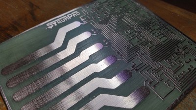 We start with [miro2424] and StrumPad. Strumpad lets you play a MIDI instrument by strumming, just like a guitar. A music keyboard acts as the guitar fretboard here – keys can be pressed to choose notes, but no sound is generated. When the strumpad is strummed, six copper strips act as capacitive sensors. Touching the strips determines which notes will be played. A piezo disc hiding below the circuit board detects how hard the notes have been strummed or tapped. The ATmega328 running the strumpad then passes the velocity and note-on MIDI messages on to a synth.
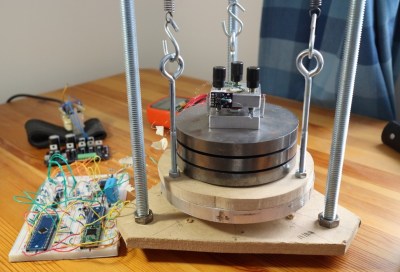 Next up is [Dan Berard] with Scanning Tunneling Microscope. Inspired by a project from [John Alexander], [Dan] created his own Scanning Tunneling Microscope (STM). The key to an instrument like this is precise movement. [Dan] achieves that by using a normal piezo disk. These disks are used as speakers and buzzers in everything from smoke detectors to greeting cards, so they’re common and cheap. [Dan] cut his piezo disk electrode into quadrants. Carefully controlling the voltage applied to the quadrants allows [Dan] to move his STM tip in X, Y, and Z. Incredibly, this microscope is able to create images at the atomic scale.
 [Thatcher Chamberlin] is next with Low-Cost Touchscreen Anywhere. [Thatcher] used a trio of Piezo disks to make any flat surface touch sensitive. The three sensors are placed at 3 corners of a rectangle. Touches with the rectangle will create vibrations in the surface that are transmitted to the piezo sensors. By measuring the vibration time of arrival, it should be possible to determine where the surface was touched. This kind of measurement requires a decent processor, so [Thatcher] is using the ARM Cortex-M0 in NXP’s LPC1114FN28. Initial tests were promising, but we haven’t heard much from [Thatcher] on this project. If you see him online, tell him to hurry up! We’re hoping to turn our parking lot into a giant electronic chess board!
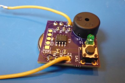 Finally, we have [Jose Ignacio Romero] with Low Power Continuity Tester. [Jose] used a Piezo element in a slightly more mundane way – as a buzzer. Who needs a whole multimeter when you’re just trying to check continuity on a few circuits? This continuity tester uses a PIC12LF1571 processor to find open and short circuits. The
 5 10 bit ADC in the PIC is plenty of resolution for this sort of tester. In fact, [Jose] even included a diode test, which emits a short beep if the leads are placed across a working diode. The PIC processor uses so little power that this tester should run for around 800 hours on a CR2032 watch battery.
If you want to see more piezo projects check out our brand new piezo projects list! If I missed your project, don’t get buzzed! Drop me a message on Hackaday.io, and I’ll add it to the list. That’s it for this week’s Hacklet. As always, see you next week. Same hack time, same hack channel, bringing you the best of Hackaday.io!


The link for “Low Power Continuity Tester” is wrong.
The right link is this https://hackaday.io/project/8467-low-power-continuity-tester
Whoops – looks like i cut off the last 7 of that project ID. All fixed now. Thanks for letting me know!
My favorite type of crystal magic!
This seismometer project is worth to add on the list …
https://hackaday.io/project/7231-seismometer-for-seismic-noise-analysis
Added – I totally forgot about that project, it was one of my favorites in the 2015 prize.
Bone? Really? Hmm i can get my hands on bones, so maybe i can reanimate a skeleton, interesting.
Bone, tendon, DNA, and a few other bio materials according to Wikipedia: https://en.wikipedia.org/wiki/Piezoelectricity#Bone
DIY Scanning Tunneling Microscope – impressive
Touchscreen anywhere has a video that can not be viewed. Wouldn’t that disqualify that entry?
about the pIC12LF1571 used in the continuity tester, there is an error . It is not the ADC which as 5 bits but the DAC. the ADC is 10 bits.
Gah! fixed
Isn’t that continuity tester a bit overkill? … I’m thinking why not just a tank oscillator, a buzzer, a battery, and some wires in series with it all?
Oh, and no need to send all that power through a circuit of course. Add a transistor.
The circuit is pretty simple, just 3 resistors, the only capacitor is the decoupling cap for the microcontroller. What I found out when designing this project is that you can implement pretty advanced features without adding almost any cost in comparison to a discrete solution. At the very minimum you could remove the button and LED to get a just a very nice _latching_ continuity tester that will catch small glitches, and will act on a predictable threshold (right now set at around 150 ohms). The circuit has a standby power consumption of right around 1uA, which gives it a ridiculously large standby battery life of 10 years, while actively sampling it consumes around 200uA (conservatively 800 continuous hours of normal use). Implementing all that with discrete parts would be a lot more complicated and expensive. Not to mention it also has a “proper” audible diode tester.
True, very true. Feature wise it’s darn good for the price, not a word about that!
It was just a thought for having no idle current.
And yes, this has a predictable threshold, which is probably the most important thing. The quick hack I mentioned wouldn’t really be… ;)
Never mind actually. I just remembered that the transistor might have just as big a leakage current as the standby current here, not to mention the pull-resistor that would be required.
Booooring… where’s the bone project?!
I think I’m missing something on the continuity tester. If I put a diode in one side, then a Harbor Freight “free” meter will flow one way and not the other. So continuity is works one way, flip the leads does not work. Works both ways, it’s a short.
I’ve done this since the 70’s with my Simpson 260.
Can I go to the moon based on a 3 cent LED a 2 cent resistor and a free meter?
This one is faster as you don’t need to flip the leads, if the forward voltage is within one diode drop (0.1-0.7) it will emit a short beep, if it’s shorted out it’s a continuous beep, that way you can quickly test a lot of diodes of BJT junctions in a short time, without looking away from the probes. It mimics the behavior of the diode tester in the Fluke 179 that I used to use when I used to work in industrial electronics repair. I could test a row of 16 transistors and freewheeling diodes for shorted bases in about a minute without skipping a beat. With a LED you’d have to look away from the probes, unless you mount it in one of them :)
Ooh, I’ve been wanting a tiny continuity tester like that for years! I very much doubt I’ll ever sit down and build one based on those plans, cause I’m lazy like that, but it’s nice to know that the option is out there.
I’m (slowly) working on the next revision, I plan to put it up for sale in tindie or somesuch if there’s interest.
I think using light beams and photo transistors would be the easiest way to turn your parking lot into chess board What light beams are interrupted would indicate what squares are occupied