Switch-mode power supplies are ubiquitous. Standard off-the-shelf modules in a consistent range of form factors available from multiple manufacturers. Globalized manufacturing and trade has turned them from expensive devices into commodity parts, and they long ago replaced iron-cored transformers as the go-to choice when a high-current low-voltage mains supply is required.
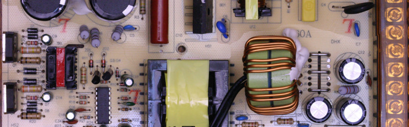
[Lindsay Wilson] faced a power supply problem for a motor he was working with, it required 7.4V and no off-the-shelf power supplies were to be found with that voltage. His solution was to take a 12V supply and modify it to deliver a variable voltage so he could dial in his requirement. A Chinese-made 12v 33A switch-mode supply was purchased, and he set to work.
In the event he was able to design a replacement feedback divider incorporating a rotary potentiometer, and achieve a voltage range of 5 to 15V. A small LED voltmeter mounted next to it in the PSU case gave him a very neat result.
Modifying a switch-mode supply to deliver a different voltage is a well-worn path we’ve covered at least once before. What makes Lindsay’s article worth a read is his reverse-engineering and examination in detail of the PSU circuit. If you’d like to learn more about all the different facets of design that go into a switch-mode PSU, it’s a detailed yet readable primer. We’d suggest reading our recent series on mains and high voltage safety before cracking open a switch-mode PSU yourself, but even if you’re never going to do it there’s something to be gained from knowing in detail how they work.
We’ve featured [Lindsay]’s work here at Hackaday a few times over the years. Check out his ultrasonic transducer power supply, which might be of use were you were building the ultrasonic soldering iron we featured not long ago, his laser stripping of ribbon cables, and his tale of decapping a USB isolator chip.


For the past few weeks I’ve been considering doing this.
He’s done it so well. I’m somewhat put off trying!
The article doesn’t seem to mention this, but if you fuck up the feedback, things WILL go boom…secondary side caps usually go first, after that then it depends on the built-in protections…(main switching transistor can explode as well)
You should have a fixed resistor parallel to the trimmer/pot, so that in case the trimmer looses contact, the PSU doen’t self-destruct.
Or even better, have trimmer/potentiometer on the “low side” of the voltage divider.
Destroyed a couple of PSUs this way :D
I agree that the voltage rating of the output capacitors leaves a little to be desired – they’re only 16V rated, so if you were running at the maximum of 15V then the lifespan probably will be shortened. However, if you need to be running at these sort of voltages, it would probably be better getting a higher-output supply in the first place (e.g. 24V).
If you look at the new feedback divider, I have designed it specifically to account for any loss of contact in the trimmer wiper. The wiper is grounded – if it loses contact, then the output will be connected directly to the IC’s feedback pin, without any division, so the IC will force the output low (well, to 2.5V), at which point the short-circuit protect will probably kick in as well. The other benefit of a grounded wiper is a linear adjustment range.
For another example of this, see my page on the 40-400V supply which uses a single transistor to buffer the feedback signal before feeding it to the potentiometer.
The feedback is a voltage divider, so it would be Vref = Vout* R1/(R1+R2) Rearranging the equation, you get the usual Vout = Vref * (1+R2/R1)
So Vout is linearly proportional to R2 and inversely proportional to R1. R1 being the ground side of the divider. I don’t see “grounded wiper is a linear adjustment range” in the math.
One of the tricks they typically do is to connect the wiper to one side of the pot and use it as a variable resistor. That was when the wiper loses contact, you’ll get the highest value and not a open circuit.
When using the “grounded wiper” configuration (actually grounded through R1), you are effectively adjusting the UPPER resistor, R2, when adjusting the pot, not the lower resistor. So, since Vout is linearly proportional to R2, you’ll get a linear adjustment range.
So your “grounded” isn’t really grounded (more like a floating), but with R1 as the lower branch. The advantage is that it would default to the lowest voltage when wiper is opened.
Doh – link here: http://imajeenyus.com/electronics/20111010_40-400V_supply/index.shtml
You can increase R3 value as your Q2 is there to provide current gain. so you wouldn’t actually need “few W”.
Could use some equalization resistors across C5 and C6 (high voltage output filter caps in series).
Shouldn’t the feedback to IC1 be connected to Wiper of your pot?
Well spotted! Good point – I had R3 as a hangover from the design without Q2 and forgot to change it.
Regarding the wiper – no, the rather odd connection is actually intentional. It both provides a linear adjustment range, and also ensures that, if the wiper loses connection with the track, the regulation loop forces the output voltage low for safety. If you just had a pot in a “normal” voltage divider configuration, the output voltage would be forced high if the wiper left the track.
I haven’t seen this sort of feedback arrangement used much (at all?), but it makes for a much nicer adjustment “experience”. As for choosing values, I mucked around at random in LTSpice until something fitted.
See here for more info on the wiper connection thing: http://imajeenyus.com/electronics/20111010_40-400V_supply/feedback_networks.pdf
See my comment on math above and about not using the pot as a divider. I can see the buffering of the divider output being a bit safer as you aren’t feeding a live voltage to a pot that the user turns.
The voltage is divided down before it goes to the pot, so that isn’t really a problem.
Interesting that the designers are still using the venerable TL494, which was the mainstay of the old PC power supplies. I once hacked a 300W PC supply to generate 13.8V at around 20A to power a converted commercial FM transceiver.
Oh, and the input “filters” on those Chinese supplies are worthless. I recently went through a half dozen from different (reputable) vendors, trying to pass FCC conducted emissions limits. Nothing would pass without an external filter (even though their data sheets all claimed they would).
“If it ain’t broke, don’t fix it” :D
But seriously, unless you need higher switching frequency or fancy DSP magic, the TL494 is the easy way to go…well documented, probably thousands of examples to base your design upon and it’s cheap and available.
btw the small-ish 12V/2A “industrial” power supply from China that I got for $10 has not filtering at all…seems to have been a little too much cost optimised :D
Absolutely concur. Those supplies are eminently hackable, and the cost of a 13.8V/20A supply, purchased at retail is enough to induce a heart attack! Whereas the 300W PC supply was free…and I had three or four available, so the consequences of failure were essentially zero (i.e.: throw out the smoking hulk and start on another).
Of course, whenever you hack something like this, it’s mandatory to do load testing with a bunch of power resistors, before connecting something expensive to your newly configured supply…
Confirmed. I built a 16KW motor controller with one.
a guy with a name “Lindsay”? first time in my life.
Have you forgot Lindsey Buckingham from Fleetwood Mac band?
Lindsey Graham, a U.S. Senator (IIRC).
It’s not as unusual as you think.
Wait ’til he finds out about Frances/Francis or Aubrey or Leslie or Patrice… ***mind blown***
One of the most beautiful hacks I ever seen here in HAD. Useful, very well documented and executed. Congratulations!
It’s so well done, it’s almost not a … well, nevermind.
Thanks! I should mention a safety aspect – a reader pointed out that there’s insufficient creepage/clearance between some of the tracks – I’ve added some info on this in red on the page.
damn. my 24V china export PSU is in many ways similar but not the same. guess i have to look it up myself
The four PC supplies I looked at were all “variations on a theme”. Take a look at the datasheet for the 494 regulator…there are applications circuits in there that are probably very close to the design of the PS you have :-)
The HHGTTG quote “almost, but not quite, entirely unlike tea” comes to mind for some reason ;-) So many Chinese products are almost, but not quite, the same, so there are often small differences between supplies.
A lot of you are speaking mandarin to me here, lol. Struggling to learn what the h— you guys are talking about
Great work, I am pleasantly surprised by the gain-phase plot. Can’t wonder why a standard 7.5V supply was not used….
Oh…..I hate you ;-) Would you believe, I never even knew that 7.5V was a standard supply voltage until you mentioned it!! When searching for supplies, I never thought to try looking for that voltage – I was only after 5,12,24 etc. Now that I look for them, there’s plenty available (e.g. http://www.trcelectronics.com/7.5-volt-power-supplies-chassis-1.shtml).
Thanks for the pointer!
Lindsay Wilson, While I see that this is an old string, I only recently found your work on reverse engineering these Chinese PSUs. Excellent work! In my application, I need to enter constant mode operation at a level equal to the PSU’s rated current. I have a capacitive load that is periodicaly discharged. The over-current mode on the devices shuts down the operation (hick-up mode) until the over-current condition is corrected. That is not acceptable. What I need is for my PSU (S-480-60) to go into constant-current at 8 amps when it sees a load requiring more than 8 amps at 60 volts. In your work, have you looked into this? Otherwise, do you have any suggestions on an approach?
I have the same psu and needed to find a variable voltage DC power supply to act as a quick fan speed conbtroller for 2 12v 80 watt DC fans acting as a room exhaust for my studio until trhe PWM speed controller came in. I had the same PSU by chance and this worked perfectly and took just 15 min. I had to use a 10k slider pot from an adjustable LED light, as I couldnt find any normal 10k pots around the house, for some reason 5v -15v ran in the upper half of the pot, and going below halfway point was a quick drop below 5v and caused the PSU to stall out and die til it was reset. I assume it was just a weird pot, b;0ut it is still going 6 months later.. running 24/7…. I am lazy.. PWM parts sitting next to it.. unused
I realize this was over a year ago, but your issue is most likely because of the two types of potientiometers- linear and audio. I could be wrong.