Drop-In Switch Mode Regulators

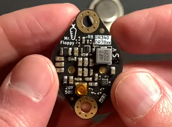
Perhaps the simplest way to regulate a DC voltage is using a voltage divider and/or an active device like a Zener diode. Besides simplicity, they have the additional advantage of not being particularly noisy, but with a major caveat: they are terribly inefficient. To solve this problem a switching regulator can be used instead, but that generally increases complexity and noise. With careful design, though, a switching regulator can be constructed to almost completely replicate a linear regulator like this drop-in TO3 replacement. (Google Translate from German)

While the replacement regulator was built by [Mr. Floppy], the units are being put to the test in the linked video below by [root42]. The major problem these solve compared to other switching regulators is the suppression of ripple, which is a high-frequency artifact that appears on the DC voltage. Reducing ripple in this situation involved designing low-inductance circuit traces on the PCB as well as implementing a number of EMI filters on both input and output. The final result is an efficient voltage supply for retrocomputers which has a ripple lower than their oscilloscopes can measure without special tools.

[root42] is not only testing these, but the linked video also has him using the modules to repair a Commodore 1541 which originally had the linear TO3 voltage regulators. It’s definitely a non-trivial task to build a switching power supply that meets the requirements of sensitive electronics like these. Switch mode power supplies aren’t new ideas, either, and surprisingly pre-date the first commercially-available transistor although modern ones like these are much less expensive to build.

Continue reading “Drop-In Switch Mode Regulators”

A Switching Power Supply, 1940s-Style

“They don’t build ’em like they used to.” There’s plenty of truth to that old saw, especially when a switch-mode power supply from the 1940s still works with its original parts. But when said power supply is about the size of a smallish toddler and twice as heavy, building them like the old days isn’t everything it’s cracked up to be.

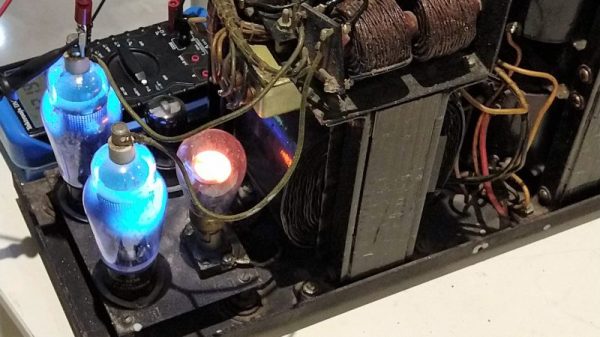
The power supply that [Ken Shirriff] dives into comes from an ongoing restoration of a vintage teletype we covered recently. In that post we noted the “mysterious blue glow” of the tubes in the power supply, which [Ken] decided to look into further. The tubes are Thyratrons, which can’t really be classified as vacuum tubes since they’re filled with various gasses. Thyratrons are tubes that use ionized gas – mercury vapor in this case – to conduct large currents. In this circuit, the Thyratrons are used as half-wave rectifiers that can be rapidly switched on and off by a feedback circuit. That keeps the output voltage fixed at the nominal 140V DC required by the teletype, with a surprisingly small amount of ripple. The video below is from a series on the entire restoration; this one is cued to where the power supply is powered up for the first time. It’s interesting to see the Thyratrons being switched at about 120 Hz when the supply is under load.

Cheers to [Ken] and his retrocomputing colleagues for keeping the old iron running. Whether the target of his ministrations is a 1974 scientific calculator or core memory from an IBM 1401, we always enjoy watching him work.

Continue reading “A Switching Power Supply, 1940s-Style”

The Pros And Cons Of Microcontrollers For Boost Converters

It never fails — we post a somewhat simple project using a microcontroller and someone points out that it could have been accomplished better with a 555 timer or discrete transistors or even a couple of vacuum tubes. We welcome the critiques, of course; after all, thoughtful feedback is the point of the comment section. Sometimes the anti-Arduino crowd has a point, but as [Great Scott!] demonstrates with this microcontroller-less boost converter, other times it just makes sense to code your way out of a problem.

Built mainly as a comeback to naysayers on his original boost-converter circuit, which relied on an ATtiny85, [Great Scott!] had to go to considerable lengths to recreate what he did with ease using a microcontroller. He started with a quick demo using a MOSFET driver and a PWM signal from a function generator, which does the job of boosting the voltage, but lacks the feedback needed to control for varying loads.

Ironically relying on a block diagram for a commercial boost controller chip, which is probably the “right” tool for the job he put together the final circuit from a largish handful of components. Two op amps form the oscillator, another is used as a differential amp to monitor the output voltage, and the last one is a used as a comparator to create the PWM signal to control the MOSFET. It works, to be sure, but at the cost of a lot of effort, expense, and perf board real estate. What’s worse, there’s no simple path to adding functionality, like there would be for a microcontroller-based design.

Of course there are circuits where microcontrollers make no sense, but [Great Scott!] makes a good case for boost converters not being one of them if you insist on DIYing. If you’re behind on the basics of DC-DC converters, fear not — we’ve covered that before.

Continue reading “The Pros And Cons Of Microcontrollers For Boost Converters”

DPS5005 Makes Digital Power Supply A Snap

Few pieces of gear are more basic to electronics than some kind of power supply. It might be a box of batteries, or it might be a high-end lab supply. [Andreas] took a DPS5005 power supply module that has USB and Bluetooth and used it to build a very capable switching power supply which he then used to build a source measuring unit.

The user interface on the diminutive module is simplistic, so [Andreas] appreciated the PC-based software that can control the supply remotely. The module can output up to 50V, but you should plan accordingly as it does need 1.1 times the maximum voltage output on the input. It will work with lower input voltages, but it just won’t be able to output as high a voltage.

Continue reading “DPS5005 Makes Digital Power Supply A Snap”

How Does A Buck Converter Work Anyway?

[Great Scott] should win an award for quickest explanation of a buck converter. Clocking in at five and a half minutes, the video clearly shows the operating principles behind the device.

It starts off with the question, what should you do if you want to drop a voltage? Many of us know that we can dim and brighten an LED using the PWM on an Arduino, but a closer inspection with an oscilloscope still shows 5V peaks that would be dangerous to a 3.3V circuit. He then adds an inductor and diode, this keeps the current from dropping too fast, but the PWM just isn’t switching fast enough to keep the coil energized.

A small modification to the Arduino’s code, and the PWM frequency is now in the kHz range. The voltage looks pretty good on the oscilloscope, but a filter cap gets it to look nice and smooth. Lastly, he shows how when the load changes the voltage out looks different. To fix this a voltage divider feeds back the information to the Arduino, letting it change the PWM duty to match the load.

In the last minute of the video he shows how to hook up off-the-shelf switching regulators, whose support components are now completely demystified as the basic principles are understood. Video after the break.

Continue reading “How Does A Buck Converter Work Anyway?”

Making A Fixed Voltage Power Supply Adjustable

Switch-mode power supplies are ubiquitous. Standard off-the-shelf modules in a consistent range of form factors available from multiple manufacturers. Globalized manufacturing and trade has turned them from expensive devices into commodity parts, and they long ago replaced iron-cored transformers as the go-to choice when a high-current low-voltage mains supply is required.

[Lindsay Wilson] faced a power supply problem for a motor he was working with, it required 7.4V and no off-the-shelf power supplies were to be found with that voltage. His solution was to take a 12V supply and modify it to deliver a variable voltage so he could dial in his requirement. A Chinese-made 12v 33A switch-mode supply was purchased, and he set to work.

In the event he was able to design a replacement feedback divider incorporating a rotary potentiometer, and achieve a voltage range of 5 to 15V. A small LED voltmeter mounted next to it in the PSU case gave him a very neat result.

Modifying a switch-mode supply to deliver a different voltage is a well-worn path we’ve covered at least once before. What makes Lindsay’s article worth a read is his reverse-engineering and examination in detail of the PSU circuit. If you’d like to learn more about all the different facets of design that go into a switch-mode PSU, it’s a detailed yet readable primer. We’d suggest reading our recent series on mains and high voltage safety before cracking open a switch-mode PSU yourself, but even if you’re never going to do it there’s something to be gained from knowing in detail how they work.

We’ve featured [Lindsay]’s work here at Hackaday a few times over the years. Check out his ultrasonic transducer power supply, which might be of use were you were building the ultrasonic soldering iron we featured not long ago, his laser stripping of ribbon cables, and his tale of decapping a USB isolator chip.

Re-Capping An Ancient Apple PSU

It sometimes comes as a shock when you look at a piece of hardware that you maybe bought new and still consider to be rather high-tech, and realise that it was made before someone in their mid-twenties was born. It’s the moment from that Waylon Jennings lyric, about looking in the mirror in total surprise, hair on your shoulders and age in your eyes. Yes, those people in their mid-twenties have never even heard of Waylon Jennings.

[Steve] at Big Mess o’Wires has a Mac IIsi from the early 1990s that wouldn’t power up. He’d already had the life-expired electrolytic capacitors replaced on the mainboard, so the chief suspect was the power supply. That miracle of technology was now pushing past a quarter century, and showing its age. In case anyone is tempted to say they don’t make ’em like they used to, [Steve]’s PSU should dispel the myth.

It’s easy as an electronic engineer writing this piece to think: So? Just open the lid, pop out the old ones and drop in the new, job done! But it’s also easy to forget that not everyone has the same experiences and opening up a mains PSU is something to approach with some trepidation if you’re not used to working with line power. [Steve] was new to mains PSUs and considered sending it to someone else, but decided he *should* be able to do it so set to work.

The Apple PSU is a switch-mode design. Ubiquitous today but still a higher-cost item in those days as you’ll know if you owned an earlier Commodore Amiga whose great big PSU box looked the same as but weighed ten times as much as its later siblings. In simple terms, the mains voltage is rectified to a high-voltage DC, chopped at a high frequency and sent through a small and lightweight ferrite-cored transformer to create the lower voltages. This means it has quite a few electrolytic capacitors, and some of them are significantly stressed with heat and voltage.

Forum posts on the same PSU identified three candidates for replacement – the high voltage smoothing capacitor and a couple of SMD capacitors on the PWM control board. We’d be tempted to say replace the lot while you have it open, but [Steve] set to work on these three. The smoothing cap was taken out with a vacuum desoldering gun, but he had some problems with the SMD caps. Using a hot air gun to remove them he managed to dislodge some of the other SMD components, resulting in the need for a significant cleanup and rework. We’d suggest next time forgoing the air gun and using a fine tip iron to melt each terminal in turn, the cap only has two and should be capable of being tipped up with a pair of pliers to separate each one.

So at the end of it all, he had a working Mac with a PSU that should be good for another twenty years. And he gained the confidence to recap mains power supplies.

If you are tempted to look inside a mains power supply you should not necessarily be put off by the fact it handles mains voltage as long as you treat it with respect. Don’t power it up while you have it open unless it is through an isolation transformer, and remember at all times that it can generate lethal voltages so be very careful and don’t touch it in any way while it is powered up. If in doubt, just don’t power it up at all while open. If you are concerned about high voltages remaining in capacitors when it is turned off, simply measure those voltages with your multimeter. If any remain, discharge them through a suitable resistor until you can no longer measure them. There is a lot for the curious hacker to learn within a switch mode PSU, why should the electronic engineers have all the fun!

This isn’t the first recapping story we’ve covered, and it will no doubt not be the last. Browse our recapping tag for more.