[HomoFaciens] is always making us feel silly about our purchases. Did we really need to buy a nice set of stepper motors for that automation project? Couldn’t we have just used some epoxy and a threaded rod to make an encoder? Did we need to spend hours reading through the documentation for an industrial inkjet head? Couldn’t we just have asked ourselves, “What would [HomoFaciens] do?” and then made a jailhouse tattoo gun attached to a broken printer carriage and some other household tech trash?
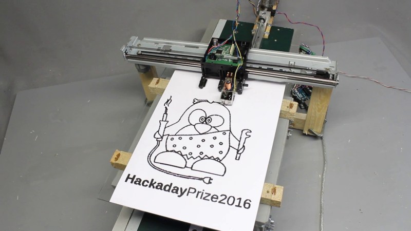
In his continuing work for his Hackaday prize entry, which we have covered before, his latest is a ink (…drop? ) printer. We think the goal is a Gingery book for CNC. He begins to combine all his previous work into a complete assembly. The video, viewable after the break, starts by explaining the function of a salvaged printer carriage. A motor attached to a belt moves the carriage back and forth; the original linear encoder from the printer is used for positional feedback.
The base of the printer is a homemade y-carriage with another salvaged printer motor and encoder driving a threaded rod. The positional feedback for this axis is provided by a optical mouse gliding on a sheet of graph paper. The printer nozzle is a cup of ink with a solenoid actuated needle in it. When the needle moves in a hole at the bottom, it dispenses ink.
As always, [HomoFaciens] makes something that is the very definition of a hack. Commenters will have to go elsewhere to leave their favorite debasement.


Original Tux > O.o tux
Thanks Gerrit for writing the article. I just want to say that the Y-axis of the printer is not using the optical mouse (of course it could be used) and the motor is not that of the printer (which would work, too). It’s a geared motor I had in stock with a sensor disc cut from a metal plate.
The video was mainly to evaluate several methods of feedback sensors for linear drives. The quality and accuracy will be examined in another video of the HackadayPrize CNC series.
Thanks for the clarification! Looking forward to that post:D
Norbert: I just want to express my compliment. You really do some amazing projects.
I always wanted to explore inkjet printer reusability, and I’m glad you pioneer in this area.
Just keep producing these awesome videos, I’ll watch each of them!:)
It looks like it draws the dots with an algorithm similar to the SCAN disk scheduling algorithm. It could be sped up by using LOOK instead, saving it from having to go to the ends of each line.
It’s printing with a command line tool that reads data from a 24bit uncompressed bitmap file (dots with R<128 or G<128 or B<128 are black). I have written the code quick and dirty, just to make the machine work for the video.
or you can do a travelling salesman route to visit all black nodes in the shortest time, but that will probably work best on relatively sparse pictures (where most of the dots on the bitmap are actually white). however, that will probably wear out the mechanics slightly faster due to the higher amount of direction changes and inertial forces. this is not a problem if the printer is slow (it should actually complete a print faster this way), but if your printer is already pretty fast, the low torque of the fast motors will probably complain a lot about the inertial changes, which will mean more overshoot, and more delay until the print head reaches the desired position, so a degradation in overall performance…
its an interesting problem to study..
You must consider that the movement along the Y axis (threaded rod drive) is clearly slower than that along the X axis, which makes your problem even harder to solve.
not really. you just need to adjust the algorithm for the “distance”. instead of the pythagorean distance, you use something else. perhaps the maximum time between movement along just the x or just the y axis. or perhaps something else. didnt quite think this through yet, just an idea.
you dont HAVE to find the perfect solution either. something along the closest next neighbor should be fairly simple to implement. or perhaps one of those TSP algorythms that employ a simulation of an ant colony. or perhaps you can write your software to apply multiple algorithms, including the ones presented here, and compare the projected total path cost of the predictions, and choose the best one.
paths generated by something like the next nearset neighbor are on average 25% worse than optimal solution, but that may still be better than scanning the whole grid. or several orders of magnitude worse, depending on the specific picture. which is why i am saying to put all of them in a software that automatically choses the quickest.
Looks like my simple machine could be used to employ a whole generation of maths and software students ;-)
I’ll keep your ideas in mind, but if a machine runs, I am usually thinking of the next hardware to build rather than optimizing the existing build…
This is really cool, but how does one print paper?
…as shown in the video. It is a sheet of paper the relay actuated needle is transferring ink to.
Maybe by pushing pulp trough a nozzle? ;)
*through
“Commenters will have to go elsewhere to leave their favorite debasement.”
I see an Arduino in the video. So at least the Arduino haters have something to go on about. :P
The Arduino isn’t connected to anything. It’s just sitting there to satisfy the “No Arduino? Not a real hack!” crowd.
Which text to speech engine is that? I want to install it.
…install a “politely comments, no offence” software on your computer, first.
+1
You have an awesome voice, put it to use! If you did more screaming in your videos, you would only get polite comments.
This is brilliant…
Norbert, im a fan. Great stuff!! Keep it
coming….
Nobody can claim “not a hack” on this one. :) I’ve been wanting to make a cnc mill for 15 years. Have slowly been accumulating knowledge and parts (and shelving it for most of that time). Started a couple times. Stopped when I realized a better way I could have done something. Basically, analysis paralysis/perfection being the enemy of good.
It’s really inspiring to see someone obviously jumping in and just getting it done, using brains and persistence in lieu of optimal parts, tools and materials.
If I can give you a tip, it’s to also just jump in and make your CNC. It’s going to be your first CNC which you’ll be able to use right away, giving you a tool to make parts for your second CNC. It will also give you the occasion to learn which mistakes to avoid and which features to add to your second one. You could start with a smaller CNC with a Dremel or similar or a trim router before making a bigger one.
If you go with a Dremel-type tool, avoid the Black & Decker RTX. Not because it’s not powerful enough but because the way its built leads to too much play at the end mill. I use an old Dremel 395 on my plywood CNC and I’ve been having a blast. I’m now designing my second CNC which will use a Mastercraft 6.5A trim router.
Just making a CNC is the quickest way to get one, but my mission is to teach future makers how build one with simple tools and how to avoid the biggest mistakes.
Yes, the router motor is an essential part of a machine and choosing a quality one is a good investment.
Thanks for sharing your thoughts.
Can’t you just brace the sway of the black & decker with some bearings you add to it? Does one really need to rely on the manufacturer alone? Or is it loose on both sides? And even then, surely you could open it up and stabilize it on the internal side too? Inside your standard dremel type device there is a classical roller skate type bearing if I recall correctly, so that should be fixable.
Very nice project. Was the servo controller from the printer not re-used because it was too difficult to id and reverse engineer?
Yes, that would be too time consuming (if possible at all) and I am behind schedule for my HackadayPrize2016 project.