Magnetic resonance imaging devices are one of the most fantastically incredible machines humans have ever built. They’re capable of producing three-dimensional images of living tissue by flipping protons around with a magnetic field. Ninety percent of the population doesn’t know what that sentence means, yet you can find an MRI machine inside nearly any reasonably equipped hospital in America.
For his Hackaday Prize entry, [Peter Jansen] is building a magnetic resonance imager, capable of producing the same type of images you’d get from the radiology department at a hospital. It’s going to be a desktop unit, capable of scanning fruit and other similarly sized objects, and can be built using tools no more advanced than a hot air gun and a laser cutter.
This project is a continuation of what should have been [Peter]’s Hackaday Prize entry last year. Things got busy for him last summer, he dropped out of the Hackaday Prize, which means he’s welcome to continue his build this year.
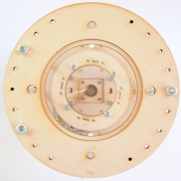
Last year, [Peter] developed the plywood mechanism that would rotate a magnetic sensor across the diameter of the scanning volume, rotate the object to be scanned, and lift the object through the volume. It’s a weird 3-axis CNC machine, basically, but the parts near the magnetic sensor can’t be made out of metal. Dental floss worked okay, but we have a few hundred feet of Spectra fishing line if we ever bump into [Peter]. Magnetic resonance imaging means big coils of wire, too, which means the tedious task of winding coils around a cylinder is part of the build. [Peter] built a machine to do the work for him.
This is not [Peter]’s first attempt at building an imaging device. He built a desktop CT scanner that is exceptionally slow, but does shoot radiation through fruit to produce an image. His first project on Hackaday.io was the Open Source Science Tricorder, one of the top five finalists in the first year of the Hackaday Prize.
Already, [Peter] has some amazing work under his belt that produces real data that could not be otherwise obtained. An Open Source MRI is the perfect project for the Hackaday Prize’s Citizen Science phase, and we’re very happy to see him enter this project.


I look forward to seeing how this one turns out.
Need to move something without using metal parts, I hear you say. Hydraulic movement using water filled syringes.
Hmm… Could you use that for solder joint inspection of BGA components too? Or is the metal from the PCB and components too much of a problem and you can only get an image with x-rays?
MRI uses strong electromagnetic fields to excite the atoms to force them to emit weak electromagnetic waves, which are registered and measured. Putting anything metal inside MRI machine will either propel it toward the electromagnet fast enough to destroy it, or induce enough eddy currents to heat it and/or destroy components by exceeding maximum voltage tolerances. If you want to see, what would happen, then drop a PCB into induction furnace…
I just checked, and wow are you right!
People with pacemakers have been messed-up because they went in for an MRI and came out with ‘burnt heart tissue’.
I honestly thought small electronics were safe but nonono they are not.
Basically an EMP blast.
I had a hospital MRI scan, and the small bits of metal inside me didn’t even tingle. I was disappointed. So YMMV.
I’ve had at least a dozen over the years, and the ligature wires in my face left over from facial surgery I had as a teen didn’t even make themselves known. My old gold wedding band wasn’t an issue, and neither is the titanium one I replaced it with (same marriage). No problem with my tattoos, both professional and DIY. Metal loops in my boots also weren’t a problem, though the staff were careful to ask me whether or not they had steel toes (nope).
There are a lot of urban legends about MRI machines, including some ridiculousness on TV shows that claim to be “medically accurate”, but the actual facts aren’t quite as strange as all that. Still, a little common sense goes a long way.
Okay guys, go and read his project page, ya?
An MRI uses a magnetic field to get the nuclei of atoms to absorb and emit a particular RF frequency (glossing over the actual QM explanation for clarity).
The higher the magnetic field, the higher the RF frequency absorbed/emitted. A medical scanner wants high *resolution*, so it uses extremely high magnetic fields so that it can use high RF frequencies for scanning.
The high RF frequencies have shorter wavelength, which makes for better resolution.
You can make an MRI machine with any field, and in principle you could make an MRI machine that operates off of the Earth’s magnetic field.
Peter’s project uses low field, so exposing metal object to the field won’t present a danger.
The defining issue with MRI is the quality of the field. Slight variations in field density within the scanning volume will make those parts absorb/re-emit a slightly different RF frequency, which causes problems for the highly-tuned receivers. You need high-Q receiver front ends to deal with noise.
Peter is attempting to compensate for field variations using coded aperture techniques, which is very interesting and AFAICT hasn’t been done before. Coded apertures are a fairly new development and are highly interesting – the Swift telescope uses one to determine the direction of gamma ray bursts.
http://hackaday.com/2015/05/29/hackaday-prize-entry-a-better-diy-ct-scanner/#comment-2586138
http://swift.gsfc.nasa.gov/about_swift/bat_images/swift_aperture.jpg
So, just to be clear. Resolution in MRI is not wavelength limited. It is SNR/time limited. Increased magnetic fields allow for higher resolution by increasing the the SNR (again, side-stepping QM). To drive this home: clinical MRI systems are mostly either 1.5T or 3T, which is 64MHz and 128MHz respectively. The wavelengths are substantially larger than the human body, yet sub millimeter resolution can be obtained with no difficulty or tricks.
Also, it is not the receivers exactly that are narrow band. Typically they have reasonably substantial bandwidth, and in for some systems are very broad band. The exception being low-input impedance amplifiers that are used to isolate the elements of array coils. The coils (similar to antennas) are, however, typically matched using a narrow band L-network. Although, this is, again, not a given. The bigger problem is actually intra-voxel dephasing, which is exhibited as very short T2* or T2**. This results in rapid signal decay, though ultra-short sequences can still be used (in some cases) and sequences more robust to T2* variation (e.g. spin-echo) can provide more latitude.
it is not the wavelength. The reason for higher fields it is to get higher SNR and do more measurements in shorter time. The SNR increases with roughly the field increase to the power of 3/2
That makes sense, the field aligns the particles which are then displaced by the RF energy so when they snap back due to the stronger field they are going to do so more energetically and give you a stronger signal. Obviously there are limits to the level of RF energy that can be safely used.
On the subject of certain moronic comments from other people, along the lines of “the metal in me did not matter”, any substance that can reflect the signal will induce echoes and multi-path problems and that will degrade the quality of the final data set.
you can’t just turn the RF energy up, the pulse have to have the right energy to flip to the right angle
the way I understand is that the resonance frequency is proportional to the magnetic field, so if we simplify imaging of a onedimensional object in a homogenous magnetic field, you have no spatial resolution, you need a gradient, so that different points of the linear object are under a different strength magnetic field, and the finer your frequency resolution, or the stronger the magnetic gradient (by having stronger magnets) increases spatial resolution. Of course tight control of the gradient, or accurate knowledge of its deviation to compensate, is necessary for good resolution…
“attempting to compensate for field variations using coded aperture techniques, which is very interesting and AFAICT hasn’t been done before”
Not sure if the German machine mentioned at minute 34 is using the same compensating technique.
https://youtu.be/TpbRpvDKy74?t=33m58s
Anyway, best wishes with the HaD project, it looks like the small size MRI devices are almost here.
I can hardly wait to have one!
It can only see hydrogen
From the Wiki:
Hydrogen is the most frequently imaged nucleus in MRI because it is present in biological tissues in great abundance, and because its high gyromagnetic ratio gives a strong signal. However, any nucleus with a net nuclear spin could potentially be imaged with MRI. Such nuclei include helium-3, lithium-7, carbon-13, fluorine-19, oxygen-17, sodium-23, phosphorus-31 and xenon-129. 23Na and 31P are naturally abundant in the body, so can be imaged directly. Gaseous isotopes such as 3He or 129Xe must be hyperpolarized and then inhaled as their nuclear density is too low to yield a useful signal…
What tesla strength is it?
how much are they paying you to promote Spectra® fishing line like this?
haha only joking.
that coil winder is the slowest thing I have ever seen.
Well, at least one hackaday editor is completely paid off by Big Spectra®. He makes far more from Big Spectra® than he does from his editing and writing duties here.
I invite you to be careful with your sensor, it’s been discontinued.
Which part has been discontinued?
Pics of objects or it didn’t happen…
Probably not a good idea for a sensor, but what about the magnetic sensors from hard drive pickups?
Scientific American had an Amateur Scientist article on building a magnetic resonance spectrometer in 1959. Not quite close enough for an “everything old is new again”, but it reminds us that some fun stuff was being done long before millennials were a stye in their parents’ eyes.
There are two projects I remember, the one that used a transition metal to boost (and widen) the signal so that 60hz sweep was possible and the other was ‘just’ a proton magnetometer. Ironically the Wadsworth magnetometer was the real deal and properly impressive but the ‘spectrometer’ was just proof of concept classroom demo and could not be made to produce useful data.
This is very impressive.
Great article here, thank you for sharing.