If you’ve worked with radios or other high-frequency circuits, you’ve probably noticed the prevalence of 50 ohm coax. Sure, you sometimes see 75 ohm coax, but overwhelmingly, RF circuits work at 50 ohms.
[Microwaves 101] has an interesting article about how this became the ubiquitous match. Apparently in the 1930s, radio transmitters were pushing towards higher power levels. You generally think that thicker wires have less loss. For coax cable carrying RF though, it’s a bit more complicated.
First, RF signals exhibit the skin effect–they don’t travel in the center of the conductor. Second, the dielectric material (that is, the insulator between the inner and outer conductors) plays a role. The impedance is also a function of the dielectric material and the diameter of the center conductor.
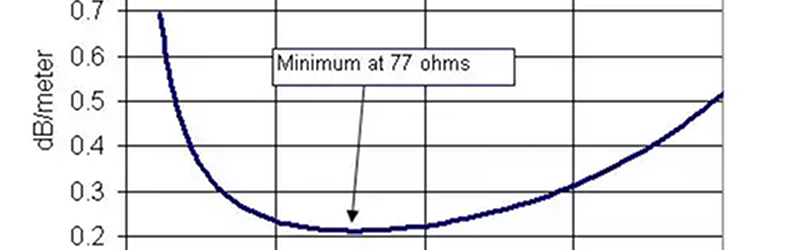
When you put all this together, you learn that the loss of the cable is minimized at 77 ohms for a cable with air dielectric. Of course, that’s not 50 ohms, right? It is close to the 75 ohms used to carry weak antenna signals in TV systems. According to [Microwaves 101], this isn’t the reason — it is related to using cheap steel for the center conductor instead of copper.
Transmitting is different. You want to handle the highest power you can manage. The peak power handling of the same cable varies with impedance. So a cable that has least loss at 77 ohms, also has maximum power handling capacity at 30 ohms. The mean between 30 and 77 ohms is 53.5 ohms.
If you want to learn more about RF design, you could do worse than watch [Michael Ossmann’s] workshop (see below). If you are more interested in coax terminations, we got you covered there, too.


Nice video. Thanks, Michael and Al.
As a relatively new HAM, I found myself asking this question. I even ran it by one of my old EE professors who was also a HAM, and he didn’t have an answer for me. Glad that I finally know. Thanks and keep up the good work!
It’s ham not HAM :)
I was once volunteering at a summer school in Inglewood, CA. Kind of like for at risk and lower socio-economic kids, some who were just out of juvenile detention. We were gonna do an outside radio experiment with FM radio and some long range HF. Another volunteer was going to bring the HF equipment who happened to be a ham operator, I was finishing up the FM radio stuff and was telling the kids that the guy was coming soon with the equipment and that he was a “ham”. I must’ve said it like 5 times referring to the guy. When he arrived, all the kids looked at me and were like “he’s HAM?”.
Cause in some places “HAM” means “Hard as A Motherfucker”, as in you go hard and train hard and you usually refer to those big diesel guys who work out all day and look tough as “HAM”. But, the ham operator was this 5’5 white guy with glasses and messy hair.
Depends on which theory of the origin of the term ham/HAM you subscribe to. I’m not sure which one is correct, but one of the theories is that H, A, & M were the first initials of the three amateur radio operators whose names were on the petition (not sure if that is the correct term) to create the legal framework for amateur radio licensing in the USA. Hiram P. Maxim was one of them (allegedly the “H” in HAM), but I don’t know the other two…
LOL… as a ham I resisted making that comment. No matter how often that it’s point out the use HAM may never die.
I like sliced ham on my bread
It’s hammer.
> it is related to using cheap steel for the center conductor instead of copper.
The impedance of a cable is determined by the dielectrical material and its thickness. The DC resistance usually have little to contribute to that.
Since the coax cable is carrying high frequency RF signals, the center conductor is not critical. The steel is probably there for mechanical strength. Skin effects depth for 600MHz (UHF) signal is only 2.6616μm, so a thin plating of copper would carry most of those signals.
The lower frequency bands get some attenuations by the resistive core while the higher frequency suffers from more losses. By using a right plating thickness of copper over a more resistive core, you can actually equalize the frequency response of the cable. SATA cables uses this trick.
If you RTFA, you’ll note it says nothing about DC resistance — the material is relevant because they’re talking about mechanical properties, and particularly the inflexibility of a steel wire for 50 ohm co-ax, implicitly holding other variables constant.
According to wikipedia, a ‘half wave’ dipole at ~0.46 wavelengths has impedance of 50+0i ohms, whereas at 0.5 wavelengths impedance is ~ 72+43i. I suspect that this is the reason for the 50 ohm standard.
Sorry, I forgot the link: https://en.wikipedia.org/wiki/Dipole_antenna
That is what I have always been told in regards to why 50ohms is so common–you don’t need a balun for a halfwave dipole like you need for 75ohm operation. Plus it makes the mental math way easier to use 50ohm ;-)
The argument on coax loss seems odd to me, considering how small of a difference (below 1%) there is between 50/75ohms.
I thought the balun is needed because coax is an unbalanced transmission line while a dipole is balanced. If that’s the case, I don’t see how that would affect it – am I missing something?
Yes, it is, he meant to say: ‘matching network’.
I like your comment, and I’m definitely not trying to school you, what I’m going to write is what I wish people had written for me to read whenever this question came up: are transmission lines vs antennas now balanced or unbalanced? the perspective I will elaborate is not very popular!
small detour:
Should I view resistors as having inherent inductance?
Should I view inductors as having inherent resistance?
Both the “yes” and “no” perspectives are important. It’s the same difference between theory and practice. One really needs the theory to guide the practice, and one really needs the practice to guide the theory.
In a sence the parasitic inductance of a resistor is in most cases so irrelevant that in the theoretical introductions to electronics it is fully ignored. It makes a lot of sense to first define ideal components, and then define realistic components in terms of ideal components. So the confusion can also be viewed as a lack of vocabular specificity. Instead of “the resistor” we have “a realistic resistor” is equivalent to “an ideal resistor” in series with “an ideal inductor”
another tangential intermezzo:
a metal consists of metal grains, which in turn are single-crystals of metal-ions. (the copper single-crystals featured recently are in fact large copper grains!)
metal-ions are also charged particles, but they are ‘immobilized’ in the metal structure. Well not totally fixed, consider electromigration, the O’s and 0’s represent ions, where the 0’s are emphasized but otherwise just metal-ions. They are grouped in one-dimensional ‘crystal grains’, a current is passed through the metal in one direction, and every now and then not just electrons but also ions move:
…OOO 0OO 0OOO 0OO 0OO 0O…
…OOO0 OO0 OOO0 OO0 OO0 O…
Observe that while some of the simplices (emphasized ions) move to the left, the complexes (grains) move to the right :-)
So in fact a “single conductor” actually is 2 conductors: the usual electrons that dominate make-up of current flow, and the metal-ions with negligible current flow.
So the current in the ‘electronic conductor’ carries current, while the ‘ionic conductor’ hardly any at all, but it is still a conductor, which carries approximately zero current.
In this sense a single metal wire can be viewed as extremely unbalanced “co-axial” cable, with inner conductor of high resistivity.
Now consider the flow of electrons in a dipole antenna: the metal ions stand still, while the electrons move in a dead-end street -> unbalanced
Now consider the flow of electrons in a loop antenna: it’s like a coax with the inner conducting ions at rest, while the electrons are on a merry-go-round -> unbalanced
So ideal antennas are unbalanced (if you think about it, suppose instead every electronic current was matched by an opposing ionic current, the electromagnetic waves generated by each would be cancelled making for a poor antenna and hence a non-ideal one), as for example the loop antenna from this perspective has 4 terminals: the ionic and electronic terminal at one end of the loop, and the ionic and electronic terminals at the other end of the loop, each end is unbalanced. This is so obvious, and the current in the ionic conductor so low, that people gloss over it, and refuse to see this pattern.
Now consider a transmission line: the ideal transmission line is lossless, and hence every local current should be balanced by an opposing local current (i.e. as close as possible to the first) so as to prevent electromagnetic waves to be emanated out of the transmission line, so in this sense ideal transmission lines should be balanced in the 4-terminal sense, but are again of course unbalanced in the 8-terminal perspective…
So no, no coax is an ideal transmission line, and is resistively unbalanced by imperfect design.
There is also the utilization vs the inherent property of the device. I.e. signal integrity vs operator/device integrety: the outer conductor is conventionally used for ground/earthing during fault conditions…
The RF impedance of the vacuum is 376.7 Ohms.
[ https://en.wikipedia.org/wiki/Impedance_of_free_space ]
It’s a shame that transmission lines and transmitters can’t be optimized to that value, but tradition is such a strong determinant of design in engineering!
50 ohms, that’s as many as five tens.
50 ohms is about the point at which my mind begins to wander in the company of Zen Buddhists.
Good informative article. Most people do not know that the center conductor is actually copper clad steel. I have on occasion had to get a magnet to prove this.
Actually, most ham’s doesnt buy coax with steel conductors and aluminium shield since they are a PITA to solder them, but if you crimp the connectors it works.
The COPPER PLATED steel conductor should be no problem to solder. Of course an aluminium shield is a completely different thing.
Efficiency and power handling are just two of the factors which were considered in the original research. There was another one, high voltage handling. This is extremely important when transmitting at high power. This one peaks at 60ohms. Belden has nice writeup on the subject, IMHO more informative than Microwave101’s: http://www.belden.com/blog/broadcastav/50-Ohms-The-Forgotten-Impedance.cfm
Nice link.
The “Unknown Editor” at Microwaves101 is a staunch Progressive Socialist – keep this in-mind when you delve deeply into the content of his Web site. This is just my opinion only and I’m not making any judgements in this post. I’ve been following he Microwaves101 site for ages.
When I hear staunch, I think of stuffy old 18th-19th century businessmen/upperclassmen, probably somewhat overweight. This has nothing to do with anything.
Thanks for sharing your free associations with us. Really.
thanks, but I think we’re able to think for ourselves