We’re not very far into the AI revolution at this point, but we’re far enough to know not to trust AI implicitly. If you accept what ChatGPT or any of the other AI chatbots have to say at face value, you might just embarrass yourself. Or worse, you might make a mistake designing your next antenna.
We’ll explain. [Gregg Messenger (VE6WO)] asked a seemingly simple question about antenna theory: Does an impedance mismatch between the antenna and a coaxial feedline result in common-mode current on the coax shield? It’s an important practical matter, as any ham who has had the painful experience of “RF in the shack” can tell you. They also will likely tell you that common-mode current on the shield is caused by an unbalanced antenna system, not an impedance mismatch. But when [Gregg] asked Google Gemini and ChatGPT that question, the answer came back that impedance mismatch can cause current flow on the shield. So who’s right?
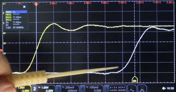
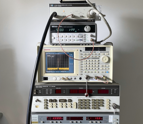
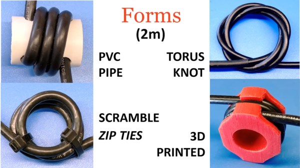
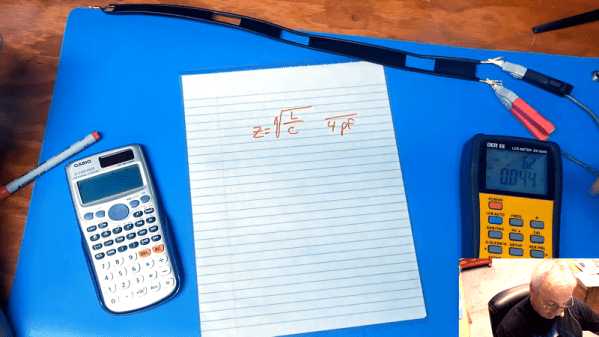
In the first video below, [Gregg] built a simulated ham shack using a 100-MHz signal generator and a length of coaxial feedline. Using a toroidal ferrite core with a couple of turns of magnet wire and a capacitor as a current probe for his oscilloscope, he was unable to find a trace of the signal on the shield even if the feedline was unterminated, which produces the impedance mismatch that the chatbots thought would spell doom. To bring the point home, [Gregg] created another test setup in the second video, this time using a pair of telescoping whip antennas to stand in for a dipole antenna. With the coax connected directly to the dipole, which creates an unbalanced system, he measured a current on the feedline, which got worse when he further unbalanced the system by removing one of the legs. Adding a balun between the feedline and the antenna, which shifts the phase on each leg of the antenna 180° apart, cured the problem.
We found these demonstrations quite useful. It’s always good to see someone taking a chatbot to task over myths and common misperceptions. We look into baluns now and again. Or even ununs.
Continue reading “Schooling ChatGPT On Antenna Theory Misconceptions”