You never know what you’ll find when you open the projects feed on Hackaday.io. Most weeks, The Hacklet follows a theme of some sort. Sometimes I find projects that just look so cool that I have to get the word out about them.
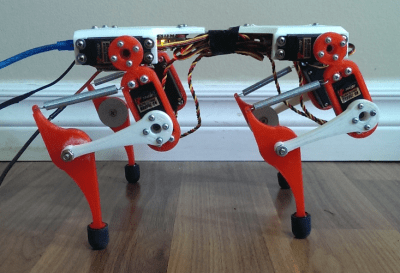
 Such is the case with this week’s first project, Mr. Runner created by [Alex Martin]. Mr. Runner is a quadruped robot that really looks the part. In fact, I’d say it looks like it’s ready to jump off the bench top. Like many of us, [Alex] has been inspired by Boston Dynamics, specifically their Wildcat robot. Wildcat had [Alex] searching the net for walking robot designs. He struck up something he liked with the work of [Dr. Fumiya Iida] and [Dr. Rolf Pfiefer]. In the mid 2000’s, the pair worked out of the University of Zurich. Mr. Runner is based upon their work, with plenty of design tweaks from [Alex].
 The basic design is a quadruped with two servos per leg. The servos are at the body and the upper half of the leg. The knee and lower leg are connected by levers and a spring, forming something of a 4 bar linkage. The spring acts as a tendon, absorbing shock, and allowing energy from the servo to be stored and released while the robot runs. [Alex] is experimenting with gaits, controlled by a PC.
Mr. Runner wouldn’t be doing much running without a way to control those 8 servos. [Alex] started with an Arduino and a LynxMotion serial servo controller. This pairing served him well for the first generation of Mr. Runner. For the new version of the robot, he’s rolling his own board based upon Lynxmotion’s
BotBoarduino. The Gerber files have been sent off to OSH Park, and in about a week, Mr. Runner will be off to the races.
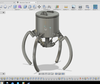
 Another great recently updated project is Arcade Claw Game Claw Build by [Alex Anderson]. I spent way too many hours of my youth in arcades, and more than a few quarters went into claw games. Sure, they’re usually rigged, but who hasn’t been pulled in by the chance to test your skill and win a prize? A friend asked [Alex] to design an arcade style claw for a game. A seasoned CNC and 3D printing master, [Alex] grabbed his notebook and started sketching. Rack and pinion designs would work well, but didn’t within the constraints of the game. A leadscrew based design would also work, but would be two expensive. Finally, [Alex] settled on a design and fired up his CAD software. He started with two jaw systems to prove out the basic system. Once that was complete, [Alex] moved to a 4 jaw setup.
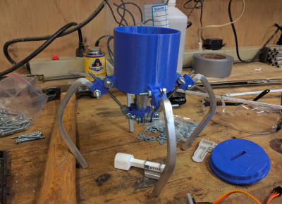
 Much like the arcade games, the claw is actuated by a central plunger. The plunger drives linkages which move the 4 claw jaws. Everything looks good on paper, but when the CAD drawings meet the real world, things get complicated quickly. The initial design relied on a 3D printed part which connected the plunger to the jaw linkages. Any slop in this part would be magnified through the rest of the mechanical system. 3D printers aren’t perfect, and there was some slop — enough that the parts would pinch and bind up while moving.
[Alex] already has a revised design in mind. This is very much a work in progress. That’s the beauty of well documented projects on Hackaday.io — you get to see what works, as well as all the trials and tribulations it took to get to a final working project. Keep at it [Alex], you’re almost there!
That’s it for this week’s Hacklet, As always, see you next week. Same hack time, same hack channel, bringing you the best of Hackaday.io!


We need moar claws! :D
I wanted to make one out of HDD head assemblies, but they are too fragile.
What I want to see and I really wish that I knew enough about CGI to do it – would be –
A forklift sized crane with a giant claw, crashing though a plasterboard wall (dry wall) in a shopping center and driving up to one of those claw machines and grabbing and lifting the whole machine with the cranes claw and then driving away with it.
That would be so satisfying to see for all those people that have been endlessly robbed by these machines. I am sure it would reach meme status.
ROFL! Haha, that is great! Those damn machines have stolen more quarters than any pinball machine ever will I’ll bet. :)
I can’t find the clip from Rocko’s Modern Life. The machine steals Rocko’s wallet and his watch. :P
A couple years ago I chatted with a vending machine contractor at a Walmart as he was replenishing machines.
He told me the contract with Walmart requires a certain percentage of “wins” with his claw machine and the bookwork to back it up. Getting a Walmart contract is having a high volume location, but they don’t want their customers to feel cheated.
Someone call Michael Bay – I want to see this!
More claws:
https://s-media-cache-ak0.pinimg.com/564x/63/39/a7/6339a7d67f4d5e5b713e93718a1f6418.jpg
Mwahahaha! My stomach hurts now. :)
Hey, Mr Fabio — how’d you miss this one? https://hackaday.io/project/11914-relayreprap
Neither rocket science nor reinventing the wheel in the /literal/ sense of the phrases — but some considerable argument could be made under the figurative meanings ;)
Very, very awesome, if you ask me — not to mention possibly cool enough to freeze nitrogen… I mean, the guy’s figured out how to make his own relays and clockwork-esque solenoid-driven stepper motors… all I can find that’s missing is a paper tape reader. (…and that may be me. I’m not sure. I didn’t go all the way back to the project gallery’s start point… too much even for me.)
…and to the project owner, will.stevens — I’m sure you’ve heard of Charles Babbage. Now look up Konrad Zuse and his Z3 and Z4 computers ;) after all, it’s his technology (relays) that you’re using there. Maybe you’ll find something useful in his work… there’s also Harry Porter over at Portland State U in Oregon, and a few others out there, who’ve built relay-based computers.
so how DOES the servo move the claws? all of the ideas presented were apparently not used so what happened? he just glued them together or something?
i would have thought an electromagnet would be how its actually done in commercial machines.
have to recommend linkage for designing these. great program. now OS on github.
– http://blog.rectorsquid.com/linkage-mechanism-designer-and-simulator/
– https://github.com/rectorsquid
not “two expensive” but “too expensive” – unless you are making two of them… :-)
I love that people pay a bit of homage to retro tech and it’s a great build and design.
Except for one thing lol. Metal staples over mains cable is in the “you should never never do this” category. You can even see at least two places where the cable has been damaged and in one location the staple is still sitting in the hole it carved into the side of the cable. Now what’s the “non-rated” insulation voltage to the staple at that point?
Mains cable should loop around a binding post of it there is not going to be any movement of the cable then drill a hole in a panel and knot the cable so that it can’t fit through the hole.
There are plenty of pre-made modules or plug-packs (wall warts) out there for people that don’t feel to confident with mains wiring.
Admittedly though, it would be hard to find a suitable supply given the higher current and voltage requirement of the audio amp.
So yeah, great build but please do something about that cable.
Knotting a mains cable is bad ju-ju.
It always ends up putting more strain on one conductor than the other which will cause it to break over time. Also, it doesn’t actually hold the cable in place as such so it can wiggle around, possibly allowing the terminations to work loose or break.
As a result, it’s expressly forbidden in the Australian/New Zealand wiring rules for example.
A screw-down clamp, cable gland or tortuous path are the preferred methods.
I must say, Mr. Runner looks awesome!
But I have concerns about the ‘Achilles heel’ ie the springs. They look like one bad bounce or fall and they might fly off. Walking/jogging/running robots are amazing and I wish the best of luck, [Alex Martin]. :D