[AA7EE] is no stranger to building radios. His latest is a from-scratch build of a 20 meter QRP transceiver based on the popular SST design. Although the SST has been available as a kit, [AA7EE] incorporated some design changes from others and some of his own, too. He even added an onboard keyer to simplify operation. You can see videos of the radio below.
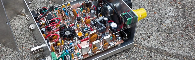
The build uses Manhattan-style PCB pads. Although the construction is very attractive, the real value of the post is the detailed explanation of not only how, but why everything is the way it is. This isn’t a simple project, and being able to see it completed step-by-step is very educational. About the only decision not adequately explained was the change of red and yellow knobs to black! You can see both versions in the videos below.
The Manhattan construction is tidy, but the radio also has an attractive case. The size is just big enough to stack a pair of paddles on top.
There may be some more enhancements for the little radio coming. We’ve covered [AA7EE’s] RF exploits before, including a physically attractive radios and details about the same construction method used in this radio.


nice cat
Quote: “Although the construction is very attractive …”
That soldering is closer to High Reliability Soldering (HRS) than anything else I have seen for a long time and apart from that, aesthetically, it looks excellent.
When you’re hand-wiring 80 components, things can get ugly real quick if you don’t keep it neat. This really is a piece of eye candy. In his write-up, AA7EE points out several times where things have moved from one picture to the next, for various reasons.
I also like his concept for modularization: he has multiple case covers, which allows him to configure the radio with different options by mounting the optional circuitry on the cover. The example he gives is an audio amp and speaker.
In circuit-layout, isn’t “ugly” a synonym for “manhattan”…? I think this blows that outta the water. “eye candy” is right.
There are those who call this style of construction “ugly”, and in the wrong hands it earns the name. The name does not apply here.
Ohh yes, that feline problem. Always wanting to be the centre of attention at the worst possible time.
Is there something you can “take” for that?
“About the only decision not adequately explained was the change of red and yellow knobs to black!”
AA7EE says:
“The yellow knob was making me uncomfortable. It has since been replaced with a black one, and I am feeling much calmer now”
love the cat lol
Very very nice soldering path. Proficiat.
Is this a Steve Webber design(dont recall callsign)? I did a similar though smaller design for 40M SSB and CW and then added a DDS tuner later. The funny thing is while I carry it when backpacking I dont really like to jabber on the radio(morse too) but building the gear is the bee’s knees!
With a10-turn pot you can have the advantage of the gear drive with your voltage tuned rig. With smaller segments of band and with calibration you can read frequency with the matching 10-turn counting dial. I have glomed on to many from old test gear or hamfests.
There are some factors that make this more of a challenge than you’re implying:
1) This radio uses a VXCO (variable crystal-controlled oscillator) for tuning. It is difficult to tune a VXCO over more than a 10-20 kHz range.
2) The transfer function from voltage to capacitance on a varactor diode is not linear.
3) The transfer function from capacitance to oscillator frequency is also not linear.
On top of all of that, it looks like the sensitivity of his tuning dial is pretty comfortable – he doesn’t have to fight with it to get his CW note right where he wants it, like within 50 Hz or so, so a 10-turn pot might make it just take longer to get to the desired frequency. His tuning range is 9 kHz, and I’m guessing his receiver bandwidth is between 500 and 1000 Hz, which means he can only resolve between nine and eighteen CW “channels” across the dial. This is just the way it is with VXCO-tuned radios – you sacrifice tuning range for stability, and the videos demonstrate the excellent stability of this design.
There are some factors that make this more of a challenge than you’re implying:
1) This radio uses a VXCO (variable crystal-controlled oscillator) for tuning. It is difficult to tune a VXCO over more than a 10-20 kHz range.
2) The transfer function from voltage to capacitance on a varactor diode is not linear.
3) The transfer function from capacitance to oscillator frequency is also not linear.
On top of all of that, it looks like the sensitivity of his tuning dial is pretty comfortable – he doesn’t have to fight with it to get his CW note right where he wants it, like within 50 Hz or so, so a 10-turn pot might make it just take longer to get to the desired frequency. His tuning range is 9 kHz, and I’m guessing his receiver bandwidth is between 500 and 1000 Hz, which means he can only resolve between nine and eighteen CW “channels” across the dial, which is a reasonable tuning speed with a single-turn pot and a big knob. This is just the way it is with VXCO-tuned radios – you sacrifice tuning range for stability, and the videos demonstrate the excellent stability of this design.