There’s hardly a day that passes without an Arduino project that spurs the usual salvo of comments. Half the commenters will complain that the project didn’t need an Arduino. The other half will insist that the project would be better served with a much larger computer ranging from an ARM CPU to a Cray.
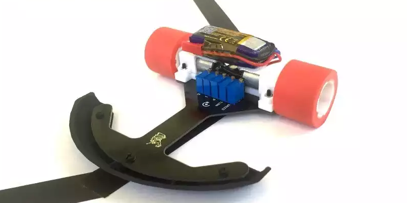
[Will Moore] has been interested in BEAM robotics — robots with analog hardware instead of microcontollers. His latest project is a sophisticated line follower. You’ve probably seen “bang-bang” line followers that just use a photocell to turn the robot one way or the other. [Will’s] uses a hardware PID (proportional integral derivative) controller. You can see a video of the result below.
Looking at how [Will] used simulation to devise a PID with opamps and a PWM generator is illustrative. As you can see from the video, the results are good.
We’ve looked at BEAM before. We’ve even seen mutants that combine traditional BEAM circuitry with microcontrollers. But it’s still nice to see the pure analog version running through its paces every once in a while.


Coulda done it with two transistors. :-P
Well for the control logic, would need output drivers.
did this with two transistors BD137, but it looses the track in sharp turns often because I had no constant turning motors
Sometimes doing things in the analog world is more satisfying. I built a small boat that would track towards a torch light placed across a small lake. A 741 op amp, two LDRs and a handful of resistors etc. did the trick. Then the boat sank :-(
God… I miss the old days – “Build Emily – the Robot With a One-Track Mind” – Popular Electronics – March 1962 – http://www.robotsandcomputers.com/robots/projects/Emily/Emily-PE0362.rar
Dang, way to prove me wrong, one transistor. Robot I was remembering was similar era, used 2 in a flip flop LDR biased each side, motor each side.
Nice find, thanks! I converted it to PDF for you, https://document.li/1PSP/
Oops.. I actually have it both ways. I meant to type PDF. I guess I saw the RAR file and that just came out my fingertips! lol.. Thanks :)
I was thinking of that, when the piece started with the bit bout not needing an Arduino. Anyone old enough would remember the time before microprocessors, when Emily roamed the earth.
I seem to recall that Carl & Jerry had an adventure related to “Emily”, or a variant.
Michael
Wow that article is fantastic imagine the controversy over the wording if used today the entire feminist squadron of flying pink and blue haired pigs would be all over it.
This project didn’t need an Arduino.
This project would be better served with a much larger computer. Something between an ARM CPU to a Cray.
How many cored will I need to read the value of the LDR? Gigs of RAM to decode the ADC value?
We usually go with one core per light sensor. That way you don’t have to worry about reading them in sequence. Just fire up four asynchronous threads, one on each proc, and let them run.
But yeah, as @lol suggests below, it’s best if you can offload the hard math to the cloud. This project could _just_ be made to run on a Raspberry Pi if you overclocked it, but it’s probably better to use AWS or something.
needs a one gig fiber on a trailing rig, with a leased line so we can borrow machine time from google’s servers, running simulations on all the possible ways a line could be drawn on a table and running predictive algorithms to pass back to the robot ;)
Can I use the fibre to send the analog light, and let AWS handle the ADC for me?
Well that was a treat.
One look at the OP-Amp circuit and now I finally have a complete understanding of PID math.
Man, it’s great to see analog still alive and kicking. Nothing wrong with doing things a different way from time to time.
This puppy is “Spyder”, and it has 4 legs, 8 motors, 0 CPUs, and 16 RC oscillators.
http://www.dailymotion.com/video/x1d65em
The arrangement of the oscillators forms a central 4 core ring that loops back on itself, and then four branches that split off from each of the 4 core oscillators. The walking gait is determined by the timing and order that the oscillators “fire”, with a plus propagating int he central ring, and fanning out as it reaches each branch.
Very cool :)
I think building a PID regulator out of OpAmps beats dragging blocks in MatLab any day. Certainly it speaks to me better. The effects of regulator constants modification can be seen in real time. Very nice!
That was a light bulb moment for me. I knew roughly how PID math works from using other peoples PID libraries for micro-controllers and never understanding them and reverting to just using the laws of physics anyway because I gave up trying to “tune” them for the intended purpose.
The op-amp circuit explained everything that I didn’t understand about PID math.
Just don’t tell anyone that the op-amp circuit is actually an analog maths computer and we can keep our secret safe from younger engineers.
Not just math, calculus!… Whenever I’m noodling something for a small system or microcontroller that runs into needing integration or a differential, I end up thinking how much easier it would be to add a couple of operational amplifiers…. only really any good if you can process your signal or output that way though.
Yes well the bandwidth is the difference. A micro-controller can be right 16 million times a second but an analog computer (op-amps) can be right *all* the time.
Well probably divide by a factor of at least a hundred, you end up using iterative methods to do a close enough guess at solution.
In practice the clock jitter on a microcontroller ruins your precision.
I’m making a ribbon controller for a synth and had the brilliant idea of measuring the ribbon as an RC constant so that when the resistive ribbon is shorted to ground, it causes a linear change in the time it takes to discharge it. So far so good, so I thought I can read it both ways on the same effort by putting the R and C in parallel and connecting it across two IO pins, from left and from right, and output two control voltages for two oscillators or arpeggiate on a single oscillator. Multitouch moog ribbon, essentially
But then, the other CV signal would be in reverse so I would have to somehow measure the “length” of the ribbon in software and subtract one of the measured delays from the total value, minus an offset the width of your finger, to get the two CVs to agree where on the ribbon you’re touching.
And that proved to be an issue because the clock jitter and drift on the micro at 8 MHz on the internal oscillator meant that the code execution never quite agreed on how long the ribbon was and the two CVs kept jumping about. If you put your finger on the chip, the values would change.
So I did the exact same thing by passing a constant current in through both ends of the ribbon, out to ground through the middle where the user touches it, and amplified the voltages at the ends of the ribbon with op-amps – one of them was an inverting amp with a user-adjustable offset with a simple potentiometer, and that was a 75 cent solution drawn up and tested in an afternoon. It also had outputs for left, right, averaged middle, and I added a 555 to make a “wobble” function that can turn to chiptune arpeggio sound by disconnecting a capacitor, simply by alternating between the left and right CV signals.
Whereas the microcontroller solution took me a whole weekend to get up to the point where it didn’t quite work, had poor resolution, terrible jitter, and no user interface to change the offsets or calibration because that would have taken a whole other day to refactor the tightly timed code to include extra measurements.
Yet it is perfectly feasible with a microcontroller, as in mr Chan’s line follower robot which uses a PD algorithm – written in assembly!.
http://elm-chan.org/works/ltc/report.html
Analog control is great – engineers and technicians should pay more attention to it, as it provides simpler solutions. But doing analog with non-linear systems is not an easy task. That’s when digital comes in, as it provides an easy way to handle non-linear responses as well as handling discontinuities like a champ! Not to mention the flexibility to change parameters or even change the control laws completely without the need of rewiring.
But then again, each problem has it’s best solution which in term is dictated by the circumstances of the problem.
This ‘analog math computer’ concept would make an interesting article. Don’t remember learning anything like that about op-amps- of course, I’m not an EE, either.
The PID stands for Proportional, Integrated (Integral), Derived (Derivative) and these are math functions.
One is just a given proportion of the input.
One is the area under a line if the input were made into a line graph over a given period.
One is the force that would be needed to accelerate a given mass to a point specified by the input.
That is why it’s so universal.
BEAM is a specific flavour of analog electronics. This is a very cool project, but if it has formal control topologies like PID, it isn’t BEAM.
BEAM is a design philosophy, and while a number of specific circuits are traditionally considered core BEAM technologies, it does not exclude other technologies… not even op-amp circuits, analog computers, and even (gasp) microcontrollers (such as is used in the so named “horse-and-rider” topology)! I’ve seen op-amps used in BEAM robots before. Saying something doesn’t conform to a design philosophy because “it has formal control topologies like PID” is the kind of thing we heard over and over through the years by young folks coming in, thinking the only “official” BEAM robots were based on solar engines, bicores, and microcores.
I’ve been playing with BEAM since the 1990s, and have always been open to new ideas. My latest concept pairs branched microcores with Xilinx CPLD chips to create on the fly remappable network layouts. Analog Nv and Nu relaxation oscillator circuits accept signals from the CPLD and from sensors. The outputs are able to be re-routed digitally, inside the CPLD (Don’t forget that the output of these circuits is a digital signal). This differentiation has always been a decisive issue in early BEAM/neural/analog design philosophies. If you look into the work in the late 1980s, early 1990s by Misha Mahowald with her silicon retina chips. They were leading edge research back in those days, but she needed a way to gat a lot of analog data out of two chips and into a single third chip in order to create her stereoscopy chip. Even back then, there was a debate on what constituted a “valid” technology… In her case, she was trying to recreate biological neurons with her retina chip. The simplest way to get it to work, was to digitally send an “address” to indicate a particular neuron fired. The receiving device would recreate that neuron firing with an appropriate neuronal spike generated at the intended destination. Back in those days, people PASSIONATELY debated whether digital addressing systems like that were “acceptable” or could even be included in a biologically inspired neural network system. Just like that situation, BEAM robotics often saw such semantic debates. Heck, we even had people debating the meaning of the name BEAM, over the years.
The truth is, that there is NO technology that is expressly prohibited, or even discouraged, from BEAM. It’s pretty hard to have an all Arduino robot be called BEAM… It doesn’t exactly scream BEAM design philosophies, but if you were to recreate the design philosophies, code the software to fit the particular nature of BEAM design, I’d say there’s no reason for exclusion. Heck, even Mark Tilden himself used microcontroller based emulation of BEAM designs with the BioBugs and RoboSapien toys.
Whether it’s a simple Solarbotics photovore BEAM robot kit, the PID op-amp circuit used in this line following robot, the wide variety of analog op-amp and traditional BEAM circuitry used in Bruce Robinson’s amazingly complex Hider (2 Monocores, 5 Bicores, a Tricore, a pair of Single Nv neurons, a 7 neuron chain, 11 individual Nu neurons, 2 op-amp based voltage followers, 2 op-amp based amplifiers, 6 op-amp based comparators, and an op-amp based voltage subractor), or a Scoutwalker 3 with it’s 4 Nv microcore, and attachments for a microcontroller board, or one of my circuits that maps the interconnections between a large number of Nv and Nu nodes, sensors, etc using CPLDs… It’s all fair game to call it all BEAM.
Oh yeah. I forgot to mention my OLD Quadrapod robot that used a 6 Nv node “Hexcore” in single process mode, fed through a 15 chip state machine that routed the hexcore signals to the correct motors by way of a router board, and a gait state logic board. Those two boards were all digital, save for the hexcore itself, located on one end of the router board. The design had one chip’s worth of traditional BEAM circuitry, and 14 chips of purely digital logic… That was still 100% BEAM. Just sayin’.
Cray-1 could do what, 240 MFLOPS with instruction pipe chaining? Are you sure that’s enough for line following? I’m pretty sure we’ll need an Altera FPGA with at least two million logic units so we can upload ten Cray-1s written in VHDL … 2.5GFLOPS is a lot, right?
A Cray-1s ???
Like to see that on wheels.
but those requirements are REAL,
have you looked at the system requirements of recent professional (ie paid) integrated development environments used for freakn 2mb 50mhz micros?
minimums:
1 one gig ram (for installer, can downgrade after install)
2 two gigs HDD space (1gig install temp, 1gig final)
3 super video card (requirement for video-logo upon software launch)
4 enough internet speed for timley download of an entire freakn gig
5 patientce because download “cutts off”, then again in standalone downloader
6 dotnet java flash directx updates, anything utilized to pretend this software is holy
7 im sure i missed something, theres always something
havent even mentioned communication ports
Huh easy!!!
Look at the Xilinx ISE for FPGA – about 8 gig download then about 17 gig to install.
Then you have to present your genitals on a silver platter to get a registration key.
There’s got to be an awkward display cabinet somewhere at Xilinx HQ.
“Sure there is” he said in a very high and squeaky voice.
^ Oh thank you for pointing out the absurdity of Xilinx’s ISE software! I use that monstrosity for my CPLD chips (that I pair to BEAM circuits). I think the EULA is over 1000 pages.
If you ever consider upgrading then do some research first as newer version support far less of the older CPLDs
Oh, and the icing ont he cake… After taking 3 days from beginning of the installation, to getting a functioning key…
CTD any time I click “Open” or “Save”… Really. Uuuuuuuuuhhhhh… –______–
Tempted to just drag out the old P4 running Windows XP, just to see if THAT version is still functional… >_>
The ISE was more stable on XP but even then it took a lot of hacking to get it to work. I have a batch file on my desktop called Fix_Xilinx.bat and every time the ISE creates a new problem for me to solve, I add the solution to the batch file.
The other thing is to pretend your back in the 1980’s and put it in C:\XILINX\ with only 8.3 (short) file and folder names or your sanity will end.
I wouldn’t bother dragging out the old P4. I use a quad core to reduce the ‘compile’ time.
Even on a dual core, compile time is like, have a coffee, take a shower, go visit a friend you haven’t seen for some time, take a walk in the park, come back check progress, take a vacation ….