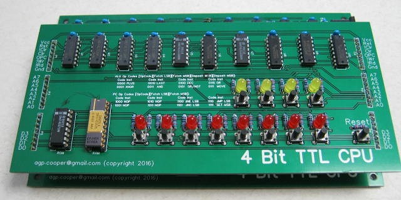
[Agp.cooper] saw a vintage 4Kx4 bit RAM chip and decided that it needed a CPU design to match. The TTL design fits on two boards and has a functional front panel.
This custom CPU project has a few interesting bits worth noting. First, it is small enough that you can wrap your head around it pretty easily. And [Agp.cooper] gives a good account of the instructions set architecture choices he considered and why he settled on the final design.

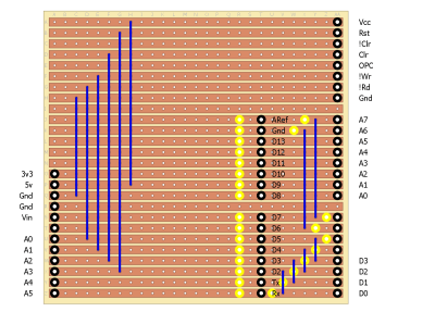
Another interesting twist is the testing. Each of the boards can mate with an Arduino which will exercise and test its functions. This allows each part of the design to test out before trying to bring up the whole CPU.
The PCBs are from EasyEDA, a service we looked at awhile back. The boards for this offering ran about $70 total, but [Agp.cooper] mentions the cost is reasonable for a one-off project, but the two-week turnaround begs for getting it right the first time lest your project sit dormant on the bench during a respin.
This is the same designer, by the way, that did the Wierd CPU, and he compares it with his 4-bit creation some in the build log.
Thanks to [starhawk] for the tip.


Hm. This looks almost simple enough to build as a mechanical computer…
That should have read….
2 boards, 1mhz, 0 cups
Congrats, you now replicated the CPU in most current ABS units :)
Given that the ABS units on most cars have a CAN bus, I’d consider that somewhat unlikely.
When the 4K x 4 SRAM was made, I was responsible for Applications engineering for SRAMs at Inmos, the manufacturer. As I recall, the 1423 had an Output Enable pin, where the industry standard 1420 didn’t, and was more difficult to use. They were made form the same die, with the pin grounded in the package. There were tons of these made.
Hey, Al, thanks for putting this up! I saw your email from the tip, and then a few hours went by and it didn’t show and I was a little concerned that it had hit the Almighty Hackaday Bit-Bucket of “Nope, That’s Actually Kinda Boring” — glad to see I was wrong :)
For the record, this project has inspired me to draw up my own 4bit CPU design. I may or may not ever have the funds to actually build it… we shall see…
Great project and it’s probably very educational for others to see logic at a more nuts and bolts level.
If you going to make a 4 bit cpu from scratch (logic gates) then I recommend that you use the opportunity for learn a hardware definition language at least for prototyping as it will save much time in testing.
Verilog and VHDL for CPLDs and FPGAs are more complex to learn but worth it. There are other simple languages like CUPL or PALASM that were used for CPLDs as well.
Here’s a project that is using PALASM, as far as I know only some burners and CPLD’s are compatible.
https://hackaday.io/project/17936-galaga-meets-iot
I actually find excitement and entertainment in working things out with actual 7400- and 4000-series parts. (Yes, I know the difference between the families, and I promise I won’t muck it up by way of interfacing LSTTL to CMOS badly.)
Dunno why… maybe it’s because I can get a fistful of them on eBay for about a buck fifty (depending on which chip we’re talking about) versus *ahem* quite a bit more for a gate array. Maybe it’s because I can’t really do SMD/SMT soldering and I’d prefer to stick to what goes down easily onto perfboard. Maybe it’s just that I think in terms of 80s-throwback chips and perfboard. Dunno.
Personally, I suspect the last option is the most correct. I do love me some 6502 goodness ;) I also enjoy playing around with relay logic… someday I hope to make a relay computer… I’ve got the design for a relay counter worked out but I need someone to machine some quarter inch acrylic for me… I have DXFs, but no money :( if anyone’s willing anyways, find me — I’m under the same username at the IO site. Failing that, take the ‘star’ out of my username here, and replace it with ‘laser’, and that’s my gmail address. (IMPORTANT: do not post the complete address, please, leave it like that — I get enough spam already. It’s okay to send me “hey is this you” emails to confirm, though.)
I agree big-time. Seeing a complete design for an extremely simple CPU demystifies the whole class. Sure, you can buy far more capable MCUs for a buck, but they are just black boxes until you see a detailed example of how they work, and it doesn’t get any better than having a detailed example that fits on a single page. And 7400/4000 series parts are themselves easy to understand – almost easier than relays since with relays you often have to chase a signal all over the schematic. With relays, the signals have to go through the relays that control them, while with electronic gates, the controlling signals to to the gates. I know that’s not very clear, but what it means is that in the schematic of a TTL or CMOS design you can arrange the gates to make the signal flow clear, while in a relay design all of the signals controlled by a single relay have to go to where the relay is, and the relay may control a number of different signals.
Relays aren’t actually *that* bad, except for the occasional “this is waaaaay too complicated” timing issue. Hysteresis is the word for that, usually ;) and –at least as I understand it– it typically refers to the fact that not all relays have identical timing characteristics, so things can get, um, confused. You wind up having to put caps on the lines to combat that, which usually slows things down enough so that the slower relays can ‘catch up’.
Of course, there’s two problems with that, if you’re wanting to compute with relays — one, it slows things down in the first place, and two, finding the right capacitor value (that doesn’t slow things down “too much” while being enough to handle the problem) usually winds up being, um, far more art than it is science.
Relays are also expensive as crap — which is why I don’t have a relay computer yet ;) I’m in the sort of economic position where I could barely afford the six 4PDT relays I need, in addition to the ones I already have from a prior failed attempt, for the counter to work… it’s not that complicated, either… an old rotary telephone dial, a double fistful of relays (fourteen IIRC), a few caps, and a few lamps (not not not LEDs) from the Late Great (?) Radio Shack. No semiconductors anywhere in the entire thing, not even for indicators — I don’t believe in cheating, even there. You spin the dial, and as it retracts (so to speak), the relays clack out the number of pulses in four-bit BCD.
Unfortunately, the friend of mine who has a CNC machine, his email suddenly died, and I can’t get in touch with him without it. (Without going into more detail here than is appropriate, that address is not coming back.) He also, last I heard, needs to order some parts for his machine. So, unless I can get someone somewhere to cut me some acrylic — and right now I don’t have any money to pay for that :( — I’m dead in the water for a bit. For the record, it’s two pieces, both smaller than 5.5″x9.5″ because that’s the maximum cutting size of his CNC.
@[starhawk]
Relays are normally ‘Make before Break’ and I think that is the issue you mean by timing. “Grey Code”is your friend with relays for this problem.
You can slow the release of normal relays by putting a copper tube over the coil. The eddy currents maintain the magnetic field for longer. You can make the release faster by increasing the air gap between the pole piece and the actuator.
AFAIK the cheapest way to make (custom) relays is with read switches, they come in both NO and NC varieties and you can wind your own formers using magnet wire and sewing machine bobbins that are cheap from China via ebay.
*reed switch*
@ROB — I’ve GOT the relays. It’s those two acrylic panels I keep mentioning, that I don’t have — they hold the relays in place, press-fit. You don’t know anyone with a machine shop in their garage, do you…?
The 74181 lives on. I was tempted to buy some of these and make a whopping big 8-bit cpu.
Personally I consider building “TTL” CPUs using black-box chips like the 74181 ALU (where the inner behavior isn’t as exposed or documented as for things like shift registers or logic gates or flip flops or whatever) cheating if the goal is to build a CPU that is simple to understand.
There was another neat design on HAD a while back that used no 74171 ALU and no 74172 register file and just used simple chips with a very simple instruction set. Wish I could find that again…
While the 74LS181 is higher integration (MSI), it isn’t a black box –
http://www.care4you.in/Tutorials/DE%20Lab/Ex-11/figure-3.bmp
https://upload.wikimedia.org/wikipedia/commons/c/c0/74181aluschematic.png