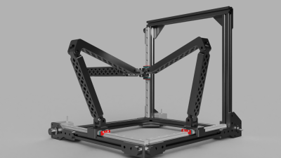
Cartesian 3D printers were the original. Then delta printers came along, and they were pretty cool too. Now, you can add tripteron printers to the mix. The Tripteron is an odd mix of Cartesian and delta. The system was invented at the robotics laboratory at Université Laval in Quebec, Canada. The team who created it say that it is “isotropic and fully decoupled, i.e. each of the actuators is controlling one Cartesian degree of freedom, independently from the others.” This means that driving the bot will be almost as simple as driving a standard X/Y/Z Cartesian printer. The corollary to that are of course delta robots, which follow a whole different set of kinematic rules.
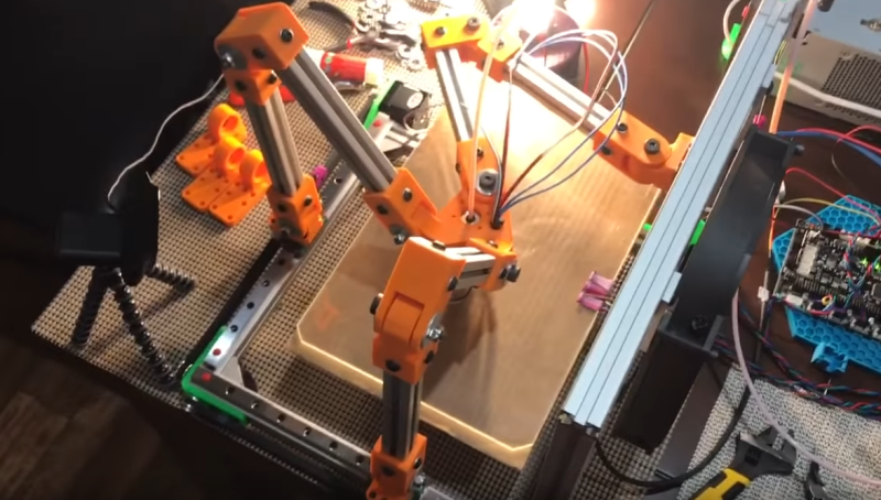
 A few people have experimented with Tripteron printers over the years, but as far as we can see, no one has ever demonstrated a working model. Enter [Apsu], who showed up about a month ago. She started a post on the RepRap forums discussing her particular design. She works fast, and has now demonstrated a working prototype making prints. Sure they’re just calibration cubes, but this is a huge step forward.
[Apsu] admits that she still has a way to go in her research — especially improving the arm and joint implementation. However, she’s quite pleased that her creation has gone from a collection of parts to a new type 3D printer. We are too — and we can’t wait to see the next iteration!


The main downside I see is that you have 3 joints on each axis that must have no deflection or backlash, yet still transfer the force of the axis to the head. Fine for a 3d printer, but not great for a milling machine.
Stiffness of the joints is an issue, but equally is stiffness of the arm segments, as they are subject to both bending and torsion. The delta configuration (ideally) keeps the moving members in tension/compression. The members subject to bending are fixed and can be made stiff enough to keep deflection below the resolution of the machine. I don’t see that being practical with this design, so it will require feedback (reflecting the deflections, bends, and twists) for long term accuracy.
All that’s required is that the deflections are less than the other errors in the system (belts, per-step-error, microstep non-linearities, etc). This is a tradeoff of material choice and design against speed and acceleration/jerk.
What does a milling machine have to do with this article?
Many a 3D printer has been converted to a milling machine. Whilst 3D printer oft don’t have what it takes to make a good mill, they do tend to give beginners a cheap way in.
‘NUFF SED.
;-)
The main downside is that this mechanism has an active patent US 6,729,202 B2. This gives the creators the right to exclude others from making it. Apsu is breaking the law by presenting this to the public and hopefully someone will notify the university that their intellectual property is being infringed upon.
Myself and others who have worked on Tripterons before me have been in contact with the inventors And the university legal department, and our understanding is that they are fine with non-commercial use as the design was never pursued in industry as many people expected it to be. It got stuck in university labs and as a “maybe someday” of hobbyists over the years. Please don’t assume that you’re the first to notice it’s patented :)
What is stopping them from suing if the design were to become popular?
Regardless of what you say this design is inherently tainted by the patent.
I wouldn’t use it for that reason alone.
I will choose to treat this comment as not a troll and reply, though the troll alarm is flickering:
Um… no.
He can not use the patented design in a product for sale (kindergarten explanation) without license.
In the US, patents have no general fair-use exemption like copyrighted works do. I believe that’s what they meant by “presenting this to the public”, i.e., admitting I made one. But as my reply indicates, I’m not the first to notice or address the patented nature.
In Canada, Canadian patent law applies.
You still wouldn’t be breaking any laws. All you are risking is that the *patent holder* may decide to sue for patent infringement. Which is extremely unlikely given the costs of such suit and the fact that this is a hobbyist tinkering with some mechanism at home (i.e. there is zero danger to any business interests). If you start building machines for sale or something like that, that could be a different story.
And publishing information about a patented invention is completely legal. Patent isn’t a trade secret, patented inventions have to be fully disclosed in order to obtain the patent!
https://cdn.img42.com/88b001e250820d5bb1acd8341af25aae.png
Sorry that’s utter nonsense.
Apsu is *not breaking any law*. Law doesn’t forbid anyone from building an otherwise patented invention or publishing information about it. The whole purpose of patents is to *disclose the idea*. And it also gives the *patent holder* something to sue you over – *if they so decide*.
If a “law was broken” you would get the state (e.g. police, attorney general, etc.) going after you. That’s not the case with patents.
See e.g. all the research around SIFT image descriptors, MPEG, etc. – nobody was going after universities doing research and using these things in their tools but e.g. the MPEG consortium was extremely vigorously enforcing their patents against any commercial users.
The patent holder is certainly not going to go after hobbyists experimenting with building RepRaps based on this idea. It poses no danger to their business and is not worth the expense of the lawsuit. However, what could get you (or him) sued is if he would use this commercially or start selling a printer based on such mechanism.
It is, indeed, not great for milling — at least not in my particular implementation of the design and material choices. Milling certainly wasn’t my goal. And yes, joint and arm link engineering is the primary challenge.
A milling machine has to ‘chip’ away at the material so the rigidity has to be greater than the force of the cutting blade or you just get friction, heat and burning rather than chipping. It’s not in the same ball park as conventional 3D printing unless you want to mill balsa wood or florists foam.
Milling machines also use ball screws or acme threads or all thread rod but never belts to get a higher force from stepper motors.
So yes, you can ‘mill’ soft materials with a 3D printer mechanics but most people think of metals when you say ‘mill’ and that is completely different to any 3D printer design.
i beg to differ on the never using belts comment. We have a Komo router table that runs belts for the x and Y axis to increase torque while lowering speed..
https://dl.dropboxusercontent.com/u/36703262/WP_20161202_09_29_46_Pro.jpg and https://dl.dropboxusercontent.com/u/36703262/WP_20161202_09_29_52_Pro.jpg
Seems that this belts are of slightly bigger dimension than in a typical 3D printer.
Carvewright has a cnc router that uses belts and is fairly accurate. It will only cut non metals as there’s no way to cool the tooling or material. I have yet to have an issue with the belts. It uses belts for all 3 axis, the x actually has large belts that move the material into position. I believe that the belts are reinforced.
actually, there is a big difference between “mill” and a “router”
Apsu is also working on some other geometries based on similar ideas but that require more complicated math.
He’s working with the Smoothie firmware for testing those : https://github.com/Apsu/Smoothieware/blob/edge/src/modules/robot/arm_solutions/ColinearTripteronSolution.cpp . Nice abstractions ftw.
That’s a lot of HWIN rails and profile just to make the process more complicated and introduce arc/angular math / irregularities into it where cartesian always worked fine…
That said: It DOES look awesome and is a cool approach – not sure about the practical side tho…
Yah, it’s kind of variable resolution across the print.
No, the resolution does not vary across the print space. Each axis is 1:1 driven.
It isn’t. Check the picture and video again.
It is constant resolution, actuation is 1:1 with effector motion. That (linearity) is the entire point of the Tripteron configuration :D
Same # of rails as a delta. Isn’t the math the same as a Cartesian? Each stepper controls one axis directly, in a 1:1 ratio.
Not sure what you mean by profile, but yeah, for footprint you need not just the frame space, but enough space for the arms to fully extend out the sides.
The math for this orthogonal configuration is, in fact, straight cartesian. There are no driven angles in the actuation, the arms are purely support/constraint systems. That is assuming the mechanical assembly is perfectly stiff, of course, and actual engineering has to deal with inaccuracy and backlash, but that’s always a tradeoff. Even your stepper motors have 5% error per step, for instance.
saying that stepper motors have 5% error per step is incorrect.
stepper motors may have an absolute error of 5% of a step, which is something very different
if each step were 5 degrees (for easy math), the error would be +- 1 degree
5% error per step would mean that after 100 steps, you can be off by +- 100 degrees
absolute error of 5% of a step would mean that after 100 steps you will still only be off by +- 1 degree
Poorly word on my part. I intended to write “step to step”. I know it’s non-cumulative, that’s a huge reason why steppers are so viable in open-loop control systems.
That’s a whole lot of joints just to avoid using linear rods and placing the X-Y carriers on the Z platform.
But it DOESN’T avoid using linear rails. Looks like the worst of both worlds, to me.
It does avoid the need for 2 parallel rails. It’s somewhat more isostatic, it won’t bind if some joints are out of whack.
You are indeed correct. The orthogonality of the joint planes prevents binding of the mechanism. It’s an ingenious approach to the kinematic constraint system and I wish I came up with it :D
I am still not sure about the battle hyperstatism vs play/flex in the system tho.
That’s part of why I’m working on the colinear Tripteron configuration now. Details are in the RepRap forum thread, including static stress simulations.
I retract my “worst of both worlds” comment. It wasn’t clear to me from the video where the positioning forces were being applied. With this added insight, I now see this as an elegant solution to the problem of combining independent motion on three axes. And great build, Apsu. Thanks for the explanations.
Thanks, and I appreciate your followup. I realize *just* this video isn’t a good demonstration or explanation of much of anything regarding the mechanics. I was literally just so excited to get to the point of reasonable behavior I grabbed a video and shared it out to everyone that was already following my detailed progress. It’s not at all obvious at a glance what’s going on when you see the arms and joints, and I too feel it’s very elegant. The Tripteron inventors are brilliant, my small part is just bringing one to life.
If you’re interested, I’m now pursuing one of the other two configurations they created (detailed in the same forum thread), which has a lot of similarities to the layout of a Delta but with linear (though not Cartesian) actuation. It’s got some different characteristics to it, but is a more compact and balanced design and my static stress simulations show incredible resilience to changing loads. I think it’s the design of the three with the most potential for printers.
Very interesting project. It looks like you have two linear rails per axis?
I am making a Arc Delta and considering inverting the forearms becau$e no Linear Rail$.
Some if the diagrams on the forum page look very interesting and I wounder if some changes to the standard Arc Delta could improve static stress capabilities. Using standard bearings would be an advantage over ball and cup.
What software are you using to analyze static stresses ?
Technically it’s not just 2-per axis, it doesn’t quite break down that way. The Inverse Kinematics for X and Y depend on which orientation you want to view the effector as having. I posted the math for the IK (and videos of motion), and you can see the actuators may all move for a some amount of X or Y. It’s still linear, though!
As for software, Fusion 360 for everything. CAD, Animation, Simulation, Rendering.
Perfect for a small compact cute little 100x100mm cube printer where there won’t be very high inertia and the little slop there is in the bearings will be negligible on that scale.
Is that the goal? High resolution in a small space? Next thing you’ll know people will be using something like SAW motors?
If China would make them the same price as a NEMA 17 stepper (and the same goes for the driver), you can bet your ass they would be all the rage ;-)
You would think SAW stuff would be easier to find and hack on… but NO…
OK, I’ll bite – What’s a SAW motor?
Surface acoustic wave. Ultra precise ultrasonic motor like what is in some camera focus mechanisms. :)
https://en.wikipedia.org/wiki/Ultrasonic_motor
Thank you [notarealemail]
I did know about surface acoustic wave devices as they were used in PAL TV’s as an analogue data delay device but I had never known that it was also used for motors.
The bearing configuration is using a duplex back-to-back preload to take up any slop there might be, riding on shoulder bolts and spreading any non-radial forces over wider areas through fender washers and thick joint bracketing. It’s an engineering challenge of material choice, dimensions and a tradeoff with speed/accel possible. But no, it’s not relegated to tiny slow printing. Just depends on how you build it.
One of the cool things with this design is that any slop in the joints isn’t multiplied throughout the mechanism.
Wow, I’m pretty excited to be featured here. It’s been a lot of work and a lot of fun getting this far. I’ll try to respond to all of the comments, but I highly suggest if you want details on Tripteron theory and to understand their benefits you read the inventors’ paper, which I’m hosting a copy of here http://propter.net/TripteronPaper.pdf
Are both the extruder and hotend from E3D? What is your opinion on the Titan?
Yes, and I was pleasantly surprised by how nice the Titan is. Works great, clever design, good materials. I’m a fan now.
I’m pleased with my E3D Lite6 so far, glad to hear about someone else giving a thumbs up for their Titan.
It’s cool that people experiment with different motion solutions but I am unsure what this is trying to solve and it introduces all kinds of problems. Rigidity of the arms and rigidity and backlash at the joints are the first things that comes to mind. It doesn’t even get rid of the over-constraint issues of linear cartesian systems like delta robots do (the joints require perfect(ish) alignment or you must live with backlash or binding.) You could say that, for this ortho-linear version, that the kinematics are simpler like a linear cartesian system but, who cares? Kinematic computation for complex systems is easily solved with the low-cost single-board computers we have access to. It doesn’t get rid of linear slides like the polar-delta or Rep-Rap Wally do.
Is there some advantage I am missing here?
There’s a laundry list of potential benefits, but you are correct that arm engineering is challenging. However, it does get rid of the primary issues of linear cartesian systems — which I see as the serial actuation coupling resulting in compounding error, and having a moving build platform. A stationary platform with linear *parallel* actuation is an obvious benefit if you can build it well.
As for backlash and binding, neither are present due to using duplex back-to-back preloaded radial bearings riding on shoulder bolts. Motion is perfectly smooth, even under medium-high preload, without any reduction in smoothness of joint rotation. The much harder problem is geometry of the links and joint brackets and material choices.
It’s not that hard to make a cartesian with a stationary build platform, it’s just very rarely done. It’s often easier to just move the build platform in Z.
I don’t know what you mean by parallel actuation vs. serial actuation.
To elaborate on what I meant, it’s certainly possible to make an XYZ gantry that moves over a stationary bed, like many of the tabletop mills are. However, it doesn’t have a great build:frame volume ratio. In a more 3d-printer-esque form-factor and expected build volume, it’s not nearly as easy. Furthermore, XYZ gantries are known as serial cartesian. Meaning that one actuator moves the next one, which moves the next one. Even a common i3-style setup is serial in XZ (Z moves X) and XZ together are parallel with Y.
Parallel actuation is any kinematic system where the movement of each axis doesn’t change the reference frame (i.e., the motor/actuator) of the others. The primary reason for parallel actuation is that error in one axis effects the coupled axes in a serial configuration, but not in a parallel one.
In theory, but in this configuration each parallel motion affects the distance from the end actuator to the linear guide, so e.g. moving in X direction changes the length of the lever to the Y axis bearing points, and changes the amount of force acting on the bearing, thereby changing the amount of slop and give.
So the advantage is pretty much lost there. The amount of wiggle in the mechanism for the Y axis is different when the X axis is all the way to one end or the other, so your backlash and loading compensation algorithms for each axis just got a lot messier.
At least with a series configuration you can estimate and compensate for the backlash and inaccuracy in each because they’re somewhat easily characterized or guessed at, but with this you got a whole non-linear system of levers going on that flexes and bends differently depending on where the entire system is going. Every single XYZ coordinate has a different amount of slop to the next.
Absolutely there are varying loads, shifting between shear and torsion. As I’ve stated repeatedly, it’s challenging engineering. However, there are varying loads in serial gantries, too. For instance Xmin vs Xmid on whatever is supporting X is constantly shifting the load distribution and magnitude of deflection. The trick is to overcompensate by achieving maximum deflections that are below the resolution of the actuation. It’s just a different system and requires a different approach.
Serial actuation is basically stacked axis. All common Cartesian system stack one axis of actuation on another axis and this means that the error of one axis is then added to the next in series.
The binding and alignment I was referring to is to be found in the joints of a single arm. The three joint axis (plural) of a single arm must be parallel or binding will ensue (or sufficient slop must exist in the bearings to tolerate the misalignment.) This is the primary benefit of a Delta of any flavor; that it is neither under nor over-constrained and therefore can be made as rigid and slop free as you like without knock-on constraints. I.E. you can make one thing more slop free without forcing another thing to have more slop or forcing improved manufacturing precision and accuracy. That is the primary disadvantage of so many of the cartesian printers out there that rely on maintaining parallelism of shafts.
As you are moving the arms with the same sort of slide as a cartesian printer, how do you get rid of any compounding error as you said? Is your assumption that three joints and a slide are more accurate in holding position than just a slide? Also, a cartesian approach using a gantry system can have a fixed bed so it isn’t an inherent problem, though I don’t see many if any 3d printers using that.
Yes, it must be parallel, which is a construction and bearing/fastener manufacturing/tolerance issue primarily. Taking up the play through preloading helps to ensure the parallelism. I’m telling you that my arms/joint systems are tightly preloaded, yet rotate smoothly, and upon measuring retain high parallelism.
As for the linear rails I’m using, their tolerances and rigidity are *vastly* higher than any other part of the printer. If you’re unfamiliar with linear guideway systems I invite you to look up their specs. With Gothic Arch raceways in particular their performance is outstanding. Thus, yes, I am considering that three joints of this design on a linear rail are very rigid and accurate. More information on my joint design is in video on my YT channel and embedded on the Thingiverse page (http://www.thingiverse.com/thing:1903757 at the bottom), but tl;dr is duplex back-to-back preloading with 8x30mm precision shoulder bolts for shafts.
And yes XYZ gantry systems exist with fixed beds, I mentioned that in another comment, they’re just not common due to build:frame volume ratios that most folks want to achieve with tabletop machines.
However stiff your joints are initially, they will be subject to wear. Having looked at the linkages a bit more, I think you can minimize the effects of that by adding appropriate counterweights to the arms so the weight of the arm more or less passes through the center of the shaft that passes through the bearings, either axially for the horizontal arm (Z axis) or radially for the vertical arms (X and Y). Also, pre-loading ball bearings is not ideal from a wear perspective, they are not typically designed for that. Pre-loaded tapered roller bearings would be a better choice for long-term reliability.
Actually they are designed for preloading, see http://www.nmbtc.com/bearings/engineering/preload/
Not preloading (or improper preloading) causes more wear, not less.
Looks like a good choice for your zero g space manufacturing fascility.
I looked at this and thought that it would have more play than conventional designs. That could be fixed by putting two bearings on each linear rail and have folding triangles instead of the arms but then you need much longer linear rails.
@Aspu, check bosch gcm 12 gdl miter saw… i think using joints like that would add substantial sturdiness to the design…
Very very cool. From reading the comments it sounds like you’ve put a lot of thought into the bearings and rails. I may have to build me one of these…
What’s the advantage? Smoother, stronger, faster, cheaper???
Thought so…
Sorry I’ve been busy. The Tripterons are very simple motion platforms in construction, and with the right material and design choices are potentially advantageous over other platforms. This one is Cartesian linear 1:1 actuation with a fixed bed and parallel kinematics, so there are many advantages with less tradeoffs. It is challenging engineering however. I’m also working on the colinear configuration if you’re interested, just google Delteron or Colinear Tripteron (or check my YT/ThingiVerse) for more information.
Nearly 9 years later